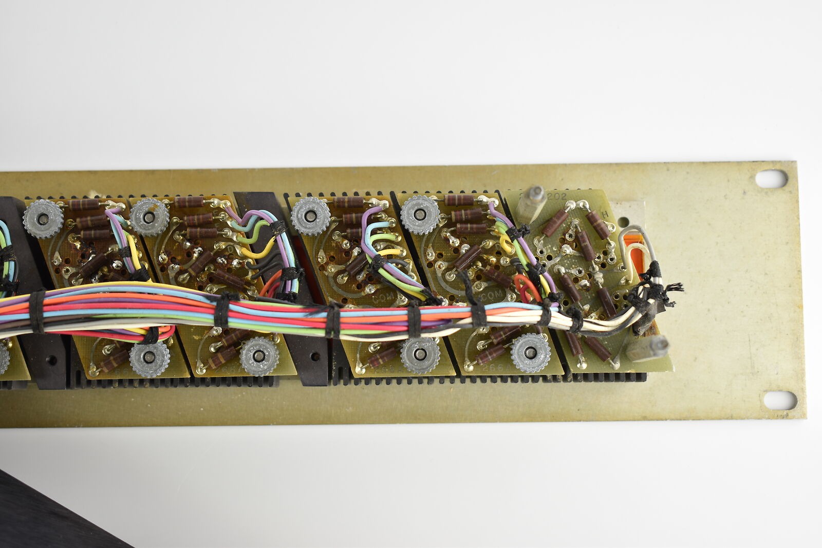
The seller from whom I bought the displays (spacemissionmarket / eBay seller: rocket-broker eBay Store) kindly sent me some photos of a partially disassembled “Type A” clock, showing the wiring and PCBs with 8 digits and +/- symbol. Thanks to Diana and the owner of the clock, these images are a tremendous help to the project. I had not seen these images when I built the LED test PCBs; they look remarkably similar, but of superior build quality, which you would expect from NASA!
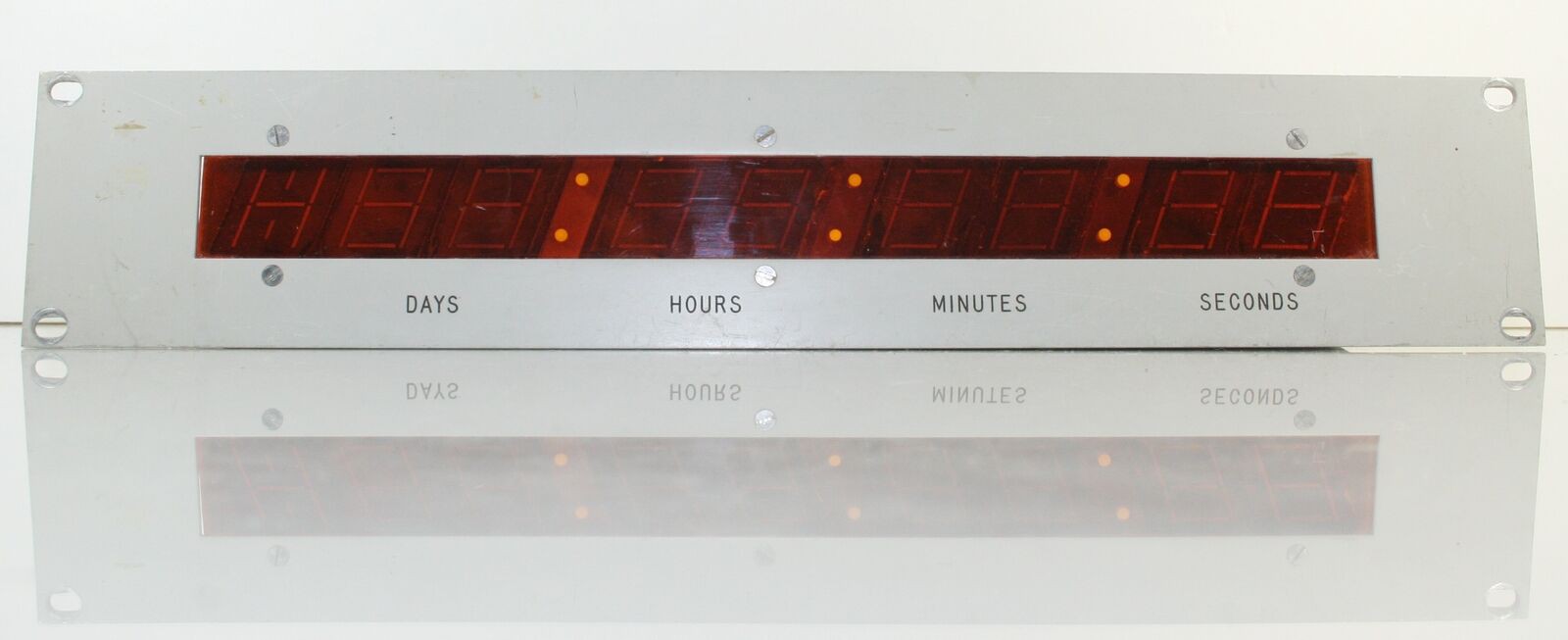
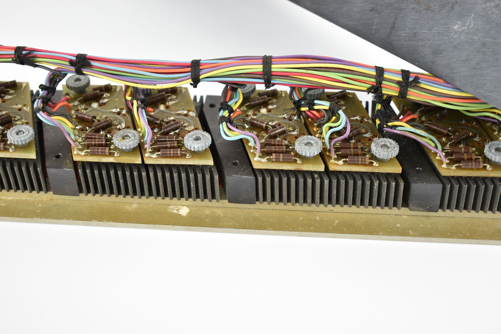
I cannot clearly make out bands on the carbon composition resistors, but it looks like brown/yellow/red which would make them 1400 ohms. A lot of aircraft control panels use ~ 28 Volts supply so perhaps these are current limiting resistors to operate 5 - 6 Volt lamps around 20-40mA?
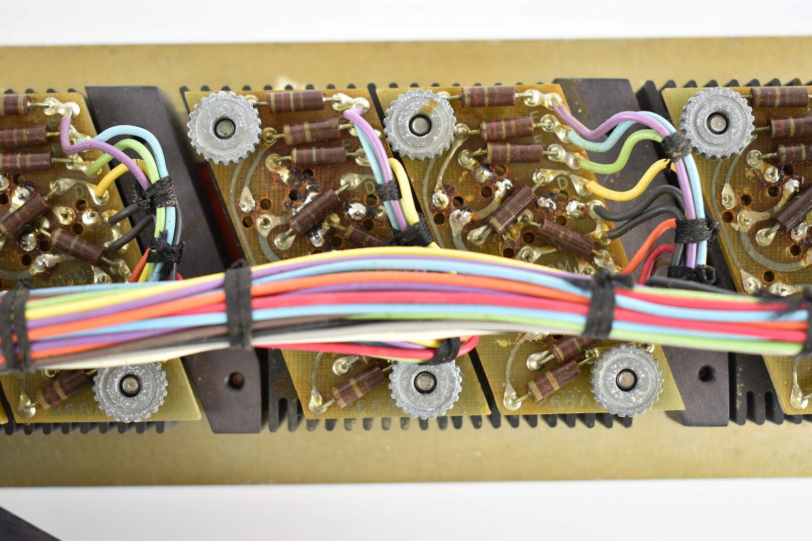
There is seriously big loom of wires; they are colour coded Brown, Red, Orange, Yellow, Green, Blue, Violet and it appears that Violet connects to segment “a”; Blue segment “b” etc… Looking at the cross section of the cut cable bundle, I’m assuming there’s a total of 56 wires for the 8 x 7 segments and 2 for the +/- indicator.
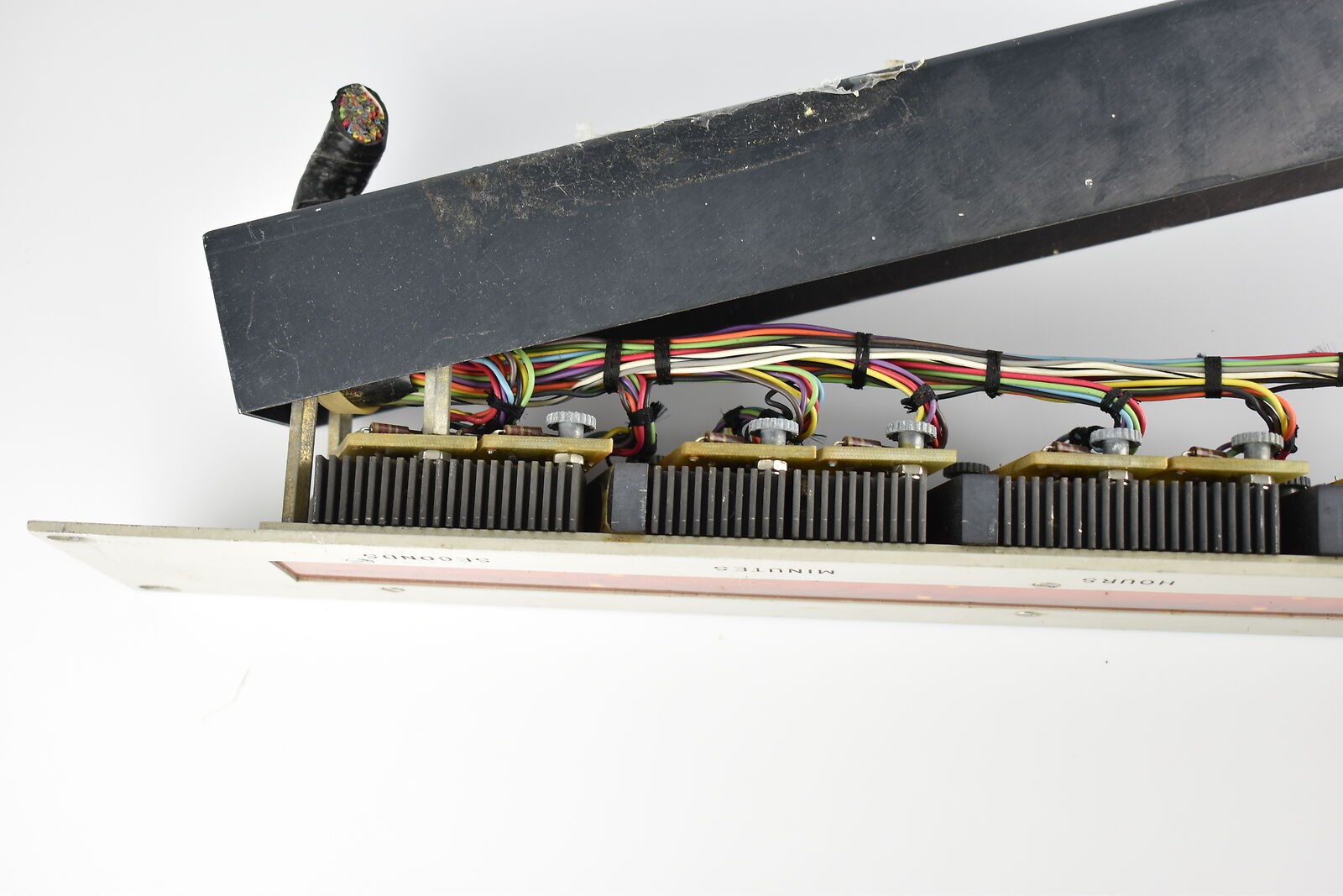
It appears that the common connection (cathode / anode?) is connected in parallel to all digits, as there are 2 black wires linked on each PCB. From this I would deduce that the displays are not driven by multiplexing, indeed if they are incandescent bulbs these would be too slow for strobe control.
I am hoping to find out more about the types of lamps used, and I am also curious about the colon separators, are these illuminated at all?
Finally, I have discovered a you tube video from Fran Blanche who has 3D printed a segment display which looks almost identical to the "Type B" units, however there is no reference to their use in the NASA control room equipment. It would be interesting to check the dimensions on the drawing files and compare to the original artifacts. Instead of 3D printing a plastic backing I would probably use a white PCB to help reflect the light through the segments.
 Patrick Hickey
Discussions
Become a Hackaday.io Member
Create an account to leave a comment. Already have an account? Log In.
I see them as Brown Red Brown which would make them 120 ohms. I don't think 5V bulbs were that common. I remember owning 12V indicator bulbs. But this is moot since you don't have to mimic the operating current, just the look.
Are you sure? yes | no