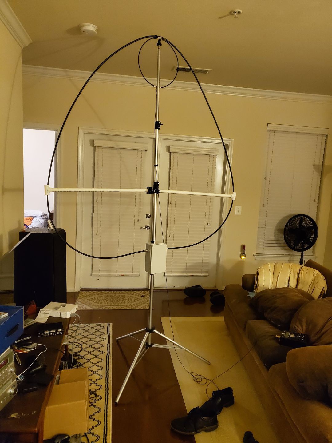
I found a 120 pf transmitting variable capacitor and mounted it into a NEMA box. (See building notes.) I cut a 5 foot loop from LMR-400 and soldered UHF connectors on the ends. I always do a careful job with coax connectors. I don't even have to connect the center pins in this design, but I soldered it carefully, anyway.
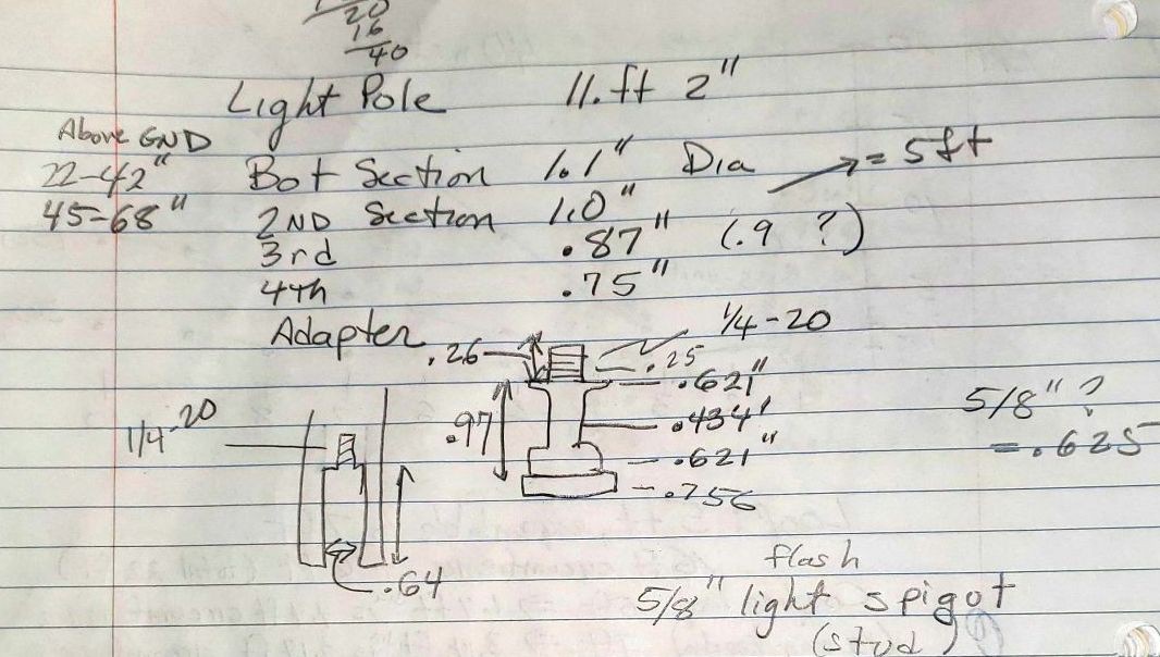
The antenna is supported by an 11-foot lighting pole. I designed 3-D printed clamps for each section of the telescoping pole (see building notes) and printed out a set. Here are my notes on the pole, including the stud on top.

The loop did not fit well inside my apartment, but I was able to get some resonance measurements.

The cross arms are PVC. The loop is more round when the arms are on the next tube up. The excitation loop is LMR-200 with the center conductor of one end tied to the shield of the other end. A BNC female Tee connector ties it to the coax feedline. J-B Weld KwikWeld two-part epoxy did an excellent job of sealing the joint and mechanically protecting the junction.
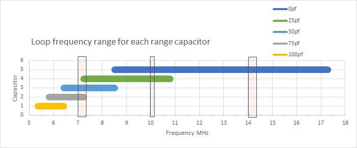
The two-section variable capacitor is effectively wired in series, giving about 50pf of adjustment range. The loop and capacitor tune from about 8.5 MHz to 17.3 MHz. For further work, I broke that into a simple model:
Equivalent capacitance = Cv + Cs + Ca
Cv = 0 to 50 pf variable
Cs = "stray" capacitance = 16 pf
Ca = fixed RF capacitors (HT50 doorknob) I add to set the range
The effective inductance, L = 5.3 uH.
This simple model has been very effective.

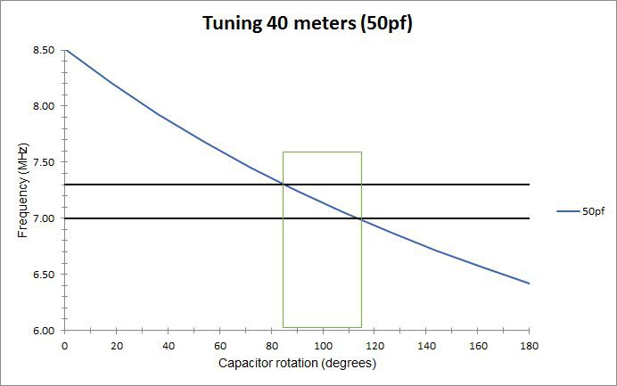
A 50 pf added fixed capacitor (Ca) gives me excellent coverage of the 40 meter band (7 to 7.3 MHz). The 40 meter band tunes over 30 degrees of rotation of the variable capacitor (which has a reduction drive on it). That is 8.4 pf out of 50 pf.

Without and added capacitor it is possible to tune 30 and 20 meters, but they only cover 2 and 4 degrees of rotation (0.56 and 1.12 pf), respectively. That is a tiny fraction of rotation. I looked at some 100 pf vacuum variable capacitors and they provide about 10 pf per turn. I am thinking about a 10 pf "bandspread" capacitor, which would eventually be motor driven.
Meanwhile, I took the prototype antenna to a friend's house. We turned to 10.136 MHz with 50 W and tried answering a DX call with FT8. The first contact was Ghana. Ok, that meets expectations. 40 meter SSB QSOs were between 1 and 2 S-units below that of an end-fed dipole. That agrees with my earlier evaluation.
Note, the very first version of the prototype used high voltage monolithic ceramic capacitors rather than RF type capacitors. They did not handle the RF current above about 8 W. As they heated up, the loop de-tuned and the SWR rose rapidly. The efficiency was probably poor at the higher powers, as well. Using the RF doorknob capacitors fixed that problem.
 Andrew Mitz
Discussions
Become a Hackaday.io Member
Create an account to leave a comment. Already have an account? Log In.