 Frank
FrankAfter identifying the need for a bigger controller, I picked the Arduino MKR Zero. The Zero has a sufficiently small footprint, generous 32K RAM, 256K Flash, and comes with a build-in MicroSD card reader. The 32bit architecture will be helpful for working with bigger data types, and the 48Mhz are much speedier, too.
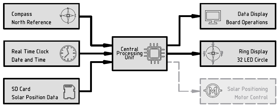
The choice of the Arduino controller determined the new system voltage to 3.3 volts. Time for PCB design, adding all components except for the stepper motor control. The board had no space left, so I decided to leave that for later.
For creating the controller board PCB design I used KiCAD 5. After two misguided attempts, the third version looked ready for production. Instead I was in for some disappointment...
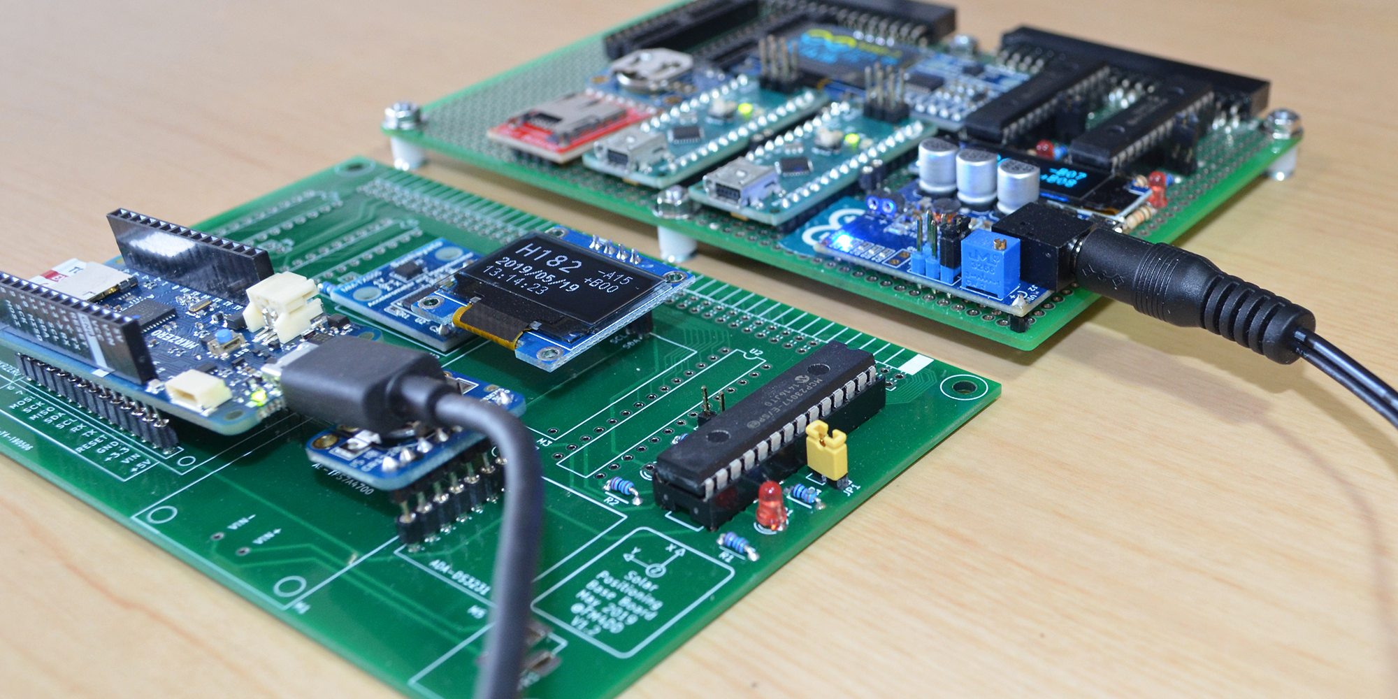
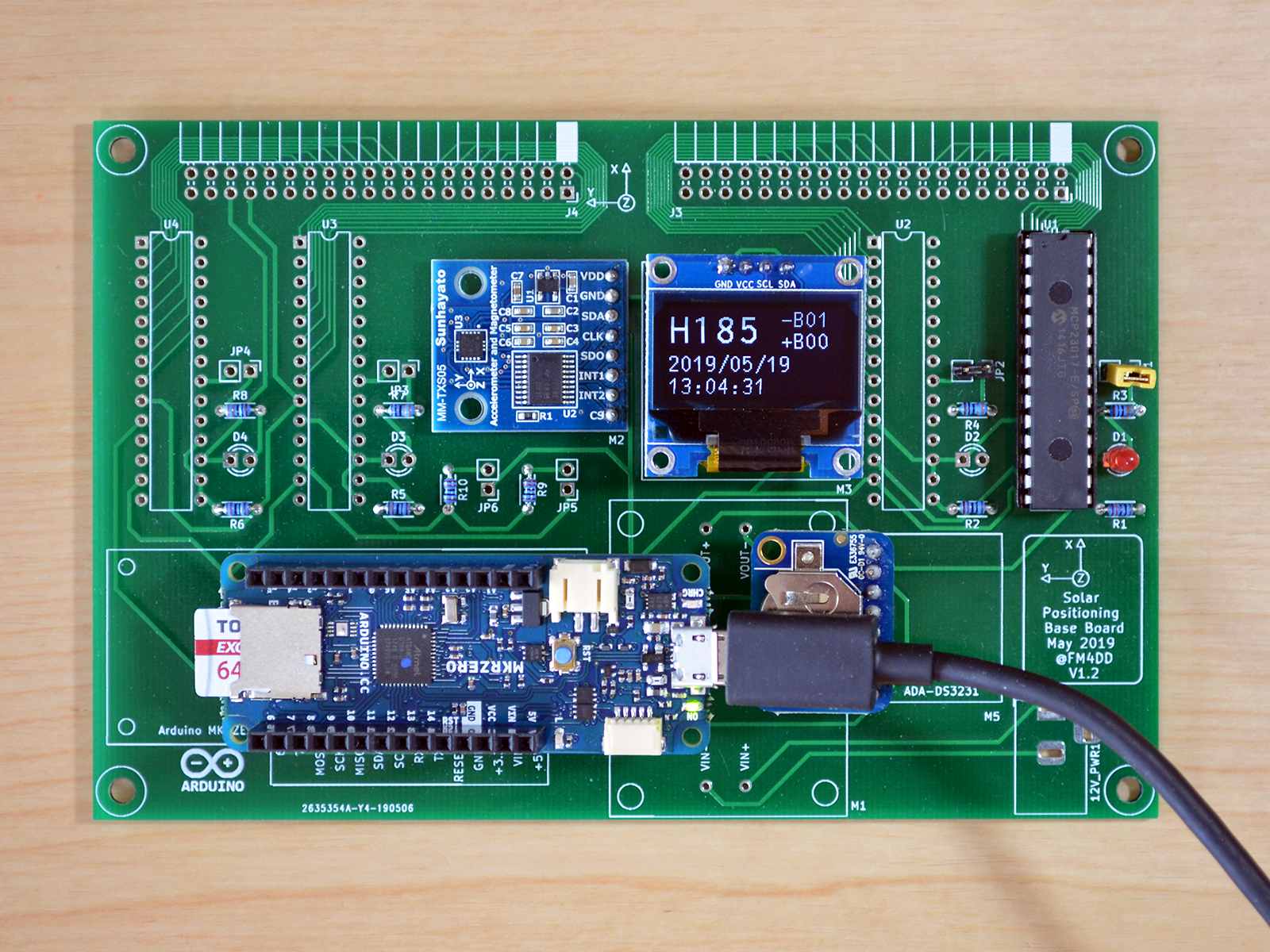
As it happens, I fell for the #1 error in PCB design: having created a mirrored footprint for the Arduino MKR Zero. How embarrassing! After finding the presentation for the top-5 footprint mistakes, it was a bit of consolation to learn that even pro's tend to make this mistake. Nevertheless I partly populated the board, using sockets to preserve modules, and turning the Arduino around to align the pins on an awkward angle. I wanted to see if the board otherwise works, and voila, the board works great, flipped Arduino pins put aside.
Discussions
Become a Hackaday.io Member
Create an account to leave a comment. Already have an account? Log In.