 John Lonergan
Half of the CPU hooked up and then I realise there's no space for a single AND gate that I needed for the program counter. control logic.

I needed a solution, then I realsed that I had some 1N4148 diodes decided to have a go at some "diode logic" to add some variation to the implementation. There was a tiny bit of spare space at the end of the control logic and so ....
I referred to this paper to understand the principles as bit better http://www.uobabylon.edu.iq/uobColeges/ad_downloads/4_22382_163.pdf
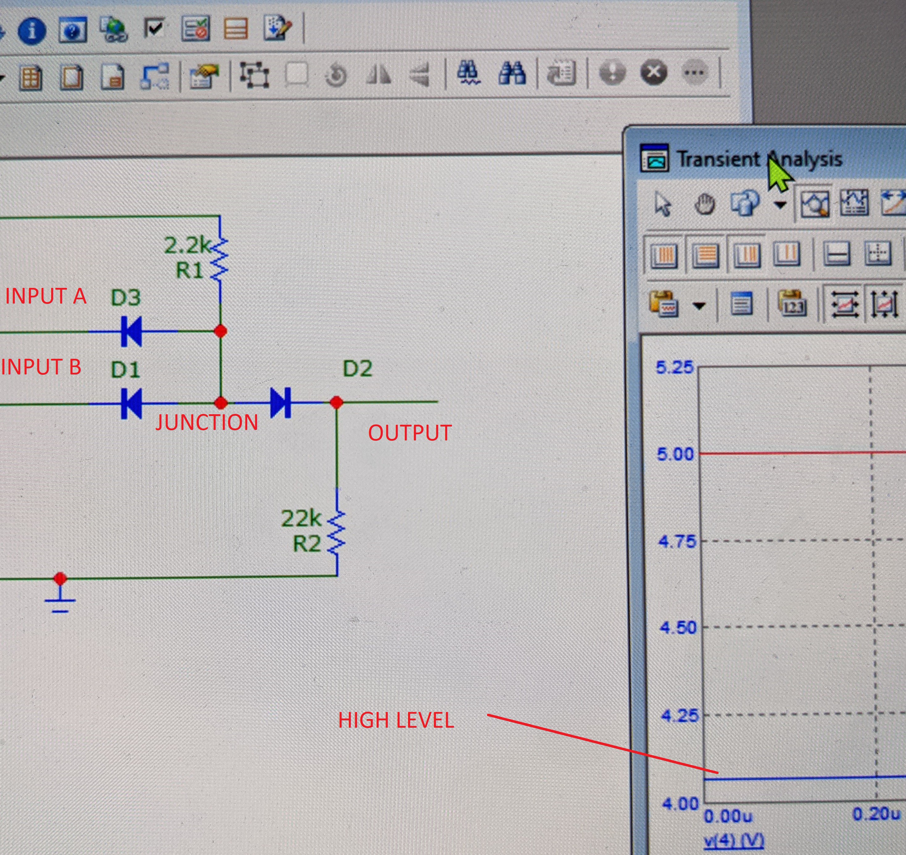
I then simulated the AND gate it on (free) Microcap 12 as shown in the screenshot below to see how the logic levels would look. Getting a low of about 300mv and a high of over 4v I decided that it was sufficient.
D2 and D1 below are the AND gate inputs and the output is via diode D2. Reading the PDF again I think I now understand why the design I was looking at had two diodes in series at the out where below I have only a single diode D2. I think it's so that it is guaranteed that the forward voltage of the output path (ie D2) would be greated than that of the the inputs. I think was to ensures that the output is biased off properly when one of the inputs is low. It prevents any current flowing to the output. I'll see how it goes without it.
You can see the three diodes the two resistors crammed into three lines on the breadboard below.
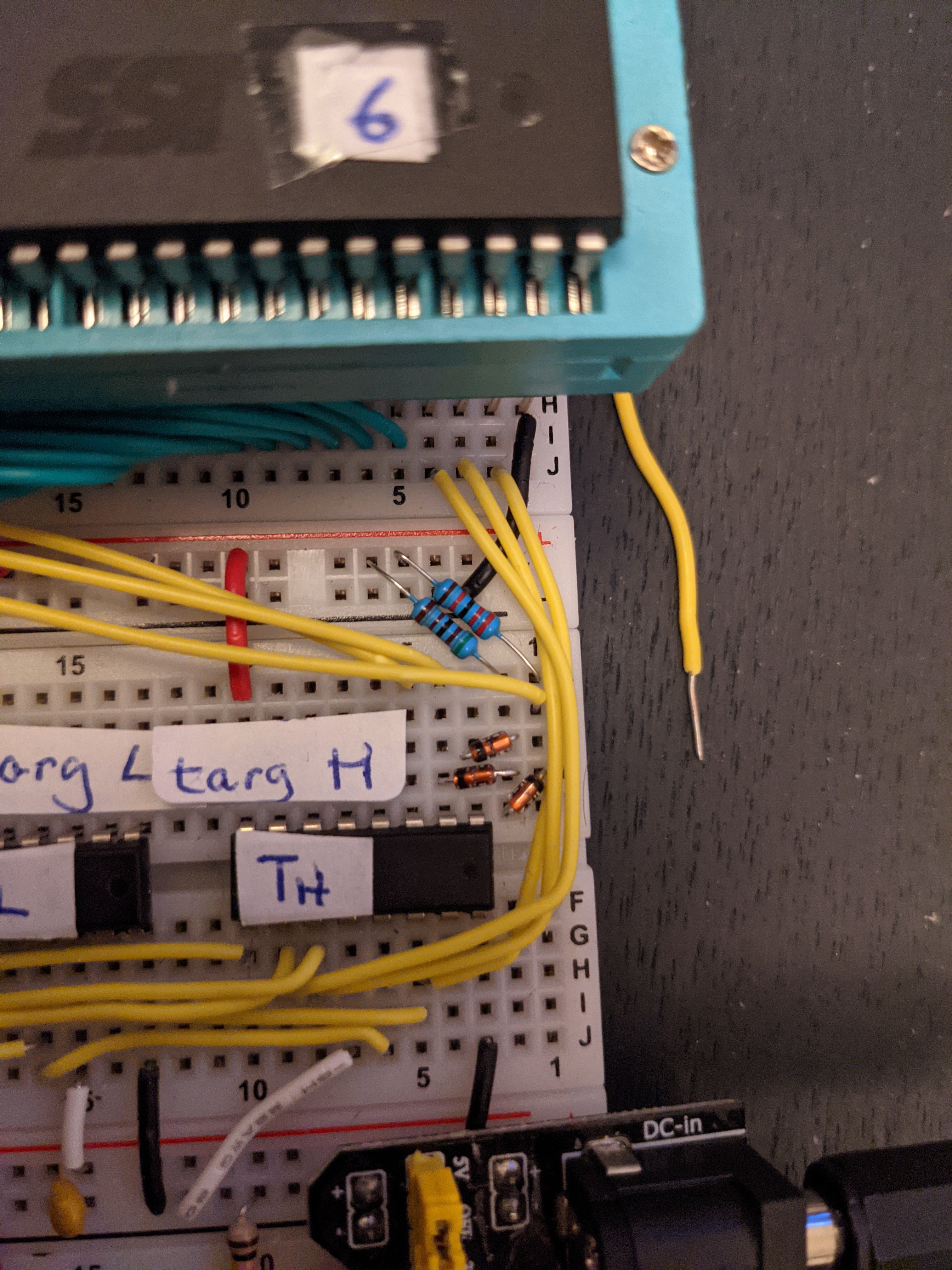 (Spot the iwiring mistake)
Discussions
Become a Hackaday.io Member
Create an account to leave a comment. Already have an account? Log In.