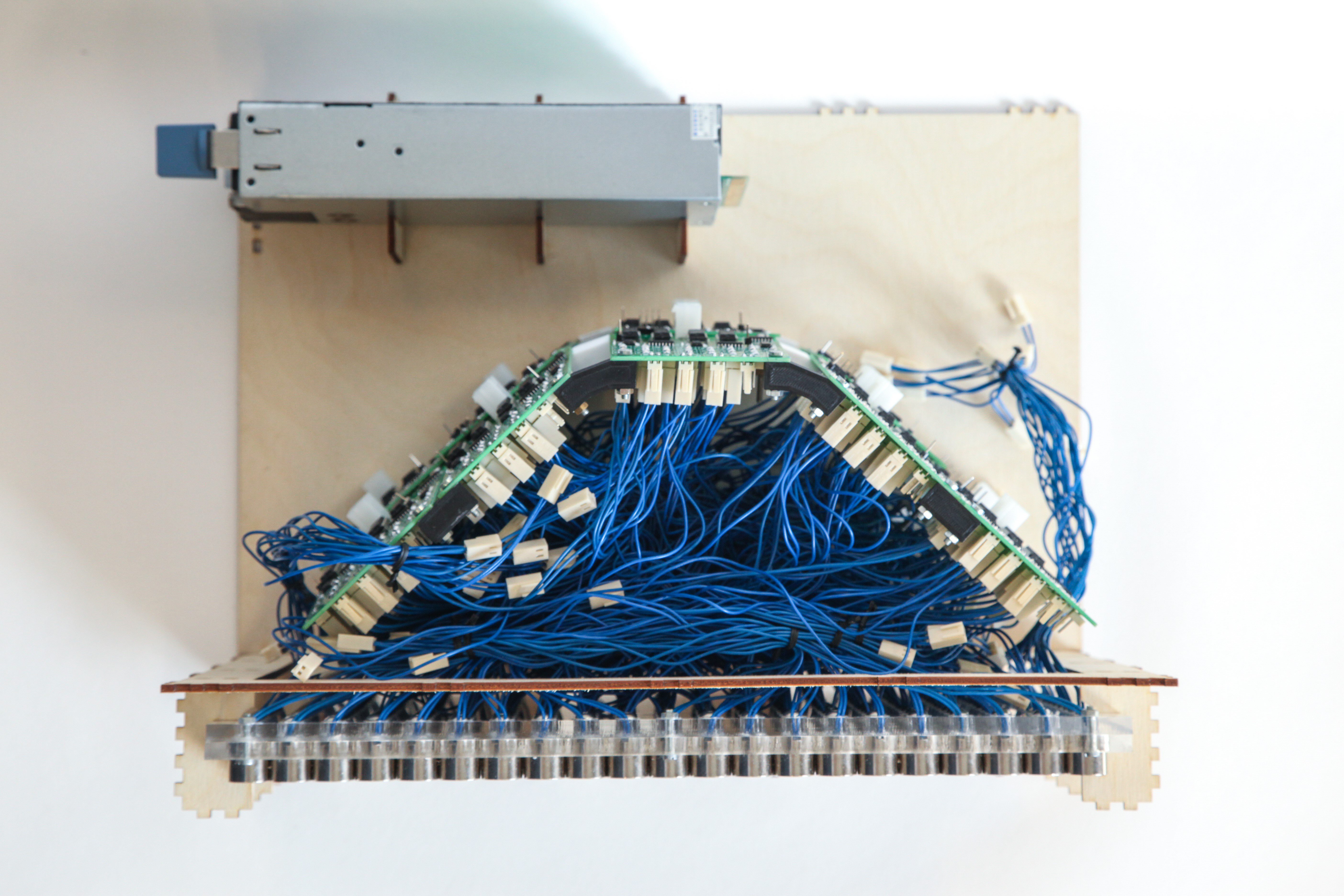
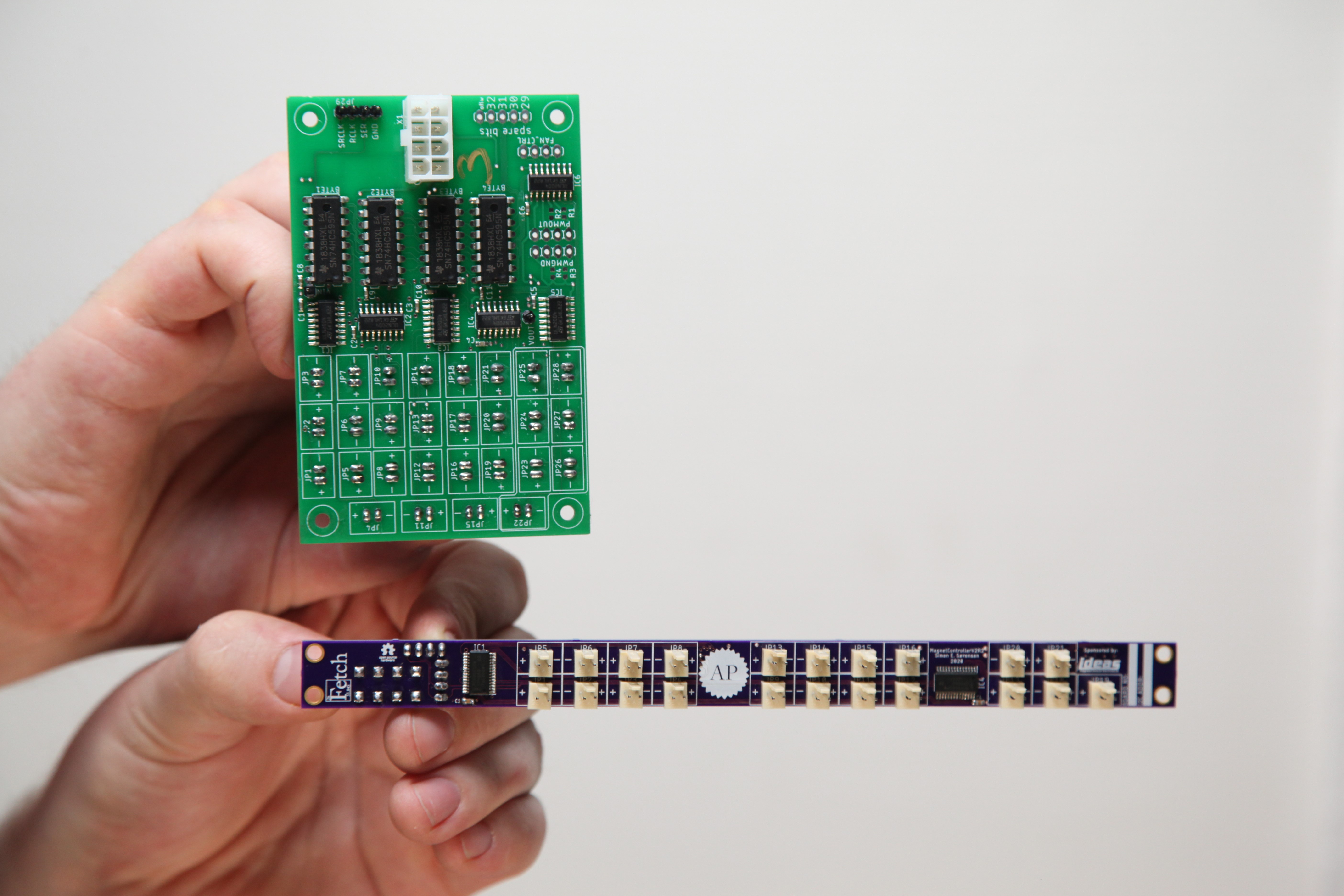
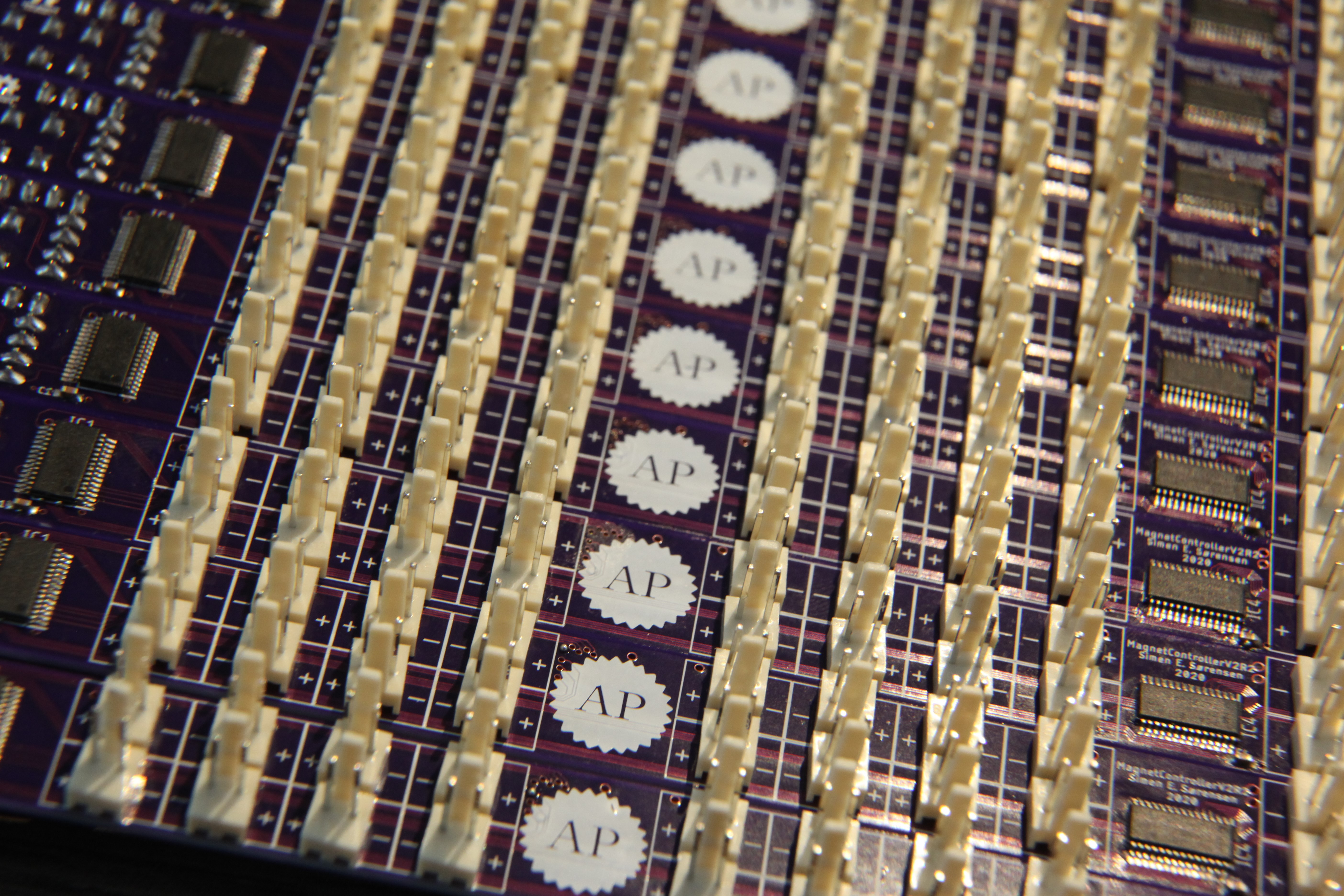
We've upgraded the Fetch hardware drastically! We are super excited to finally share what has been going on behind the scenes on this project since before COVID hit and slowed down our progress. First, have a look at our latest project update video, and then dive into the technical details below.
Project Update Video
Technical details
Why redesign?
When developing the first version of Fetch we quickly encountered a few problems that could only be solved with a complete PCB redesign. We had made the electronics too generic, and hadn't considered actual integration too thoroughly. So, when we actually attempted to attach wires to it for the first time, we soon realized that the wires weren't long enough to reach where we wanted them. Additionally, since we weren't quite sure how we wanted the software architecture to be, we implemented a lot of features that were more in the "nice to have" category than in the "need to have" category, resulting in an overall bulky design.

Apart from a poor form factor, we also soon discovered that we needed to be able to control the magnetic field strength of each individual electromagnet. The reason that this is necessary is because gravity will pull the ferrofluid down towards the bottom magnet if several pixels are ignited in the same column. The simplest way to control the magnetic field, without having to deal with any additional complex adjustable current circuitry, is by pulse-width modulating (PWM) the supply current that is fed to the electromagnets. We didn't really have a good way to do this though, as the PCBs were based on shift registers that parallelized a stream of serial data in order to open or close gates in ULN2004 Darlington transistor arrays. This means that, if we wanted to implement PWM, we had to do it in software, and the software would be highly resource consuming given that there is a lot of serial data to shift out in order to even get close to a decent PWM frequency.
Design requirements
So when redesigning the board we had much stricter design requirements, both in terms of form factor, and in terms of necessary features.
- We wanted one single board controlling each row of electromagnets to simplify the code (and we conveniently had the same number of outputs on our PSU as rows in our electromagnet matrix, which steered us towards one board per row rather than one board per column).
- We wanted the board to have a thin and wide form factor so it would fit behind the electromagnet matrix and all the wires would reach their dedicated connector.
- We wanted to use an IC that could handle PWM for us, preferably through an actual serial protocol rather than just bit shifting.
- We needed to keep the things that worked well in our previous design (such as an alternating pattern of electromagnet polarities designed into the boards rather than having to manage electromagnets with different polarities decided by their connector orientation).

The trick
Three of the mentioned requirements were easy to implement, but finding a PWM capable IC that could provide enough current for our needs proved more difficult. After pondering a while we realized that there are a ton of PWM capable ICs in the LED driver segment.
Maybe we could just use an LED driver to power our magnets? The problem with that idea turns out to be the maximum current rating. LED drivers are typically not rated to sink more current than what is necessary to turn on an LED or two. While a normal LED can consume a fair bit of current (typically up to ~20mA), it's generally not even close to the consumption of an electromagnet (~200mA).
Ok, so maybe we could combine an LED driver with a transistor array in a similar fashion to how we combined shift registers and transistor arrays before? The problem with this idea is that most LED drivers are designed to be "open-drain", meaning they are supposed to be connected to the ground side of a load and sink current that is provided by some other source. They are therefore not able to provide a logic "high" signal without an external inverter or pull-up resistor that would quickly complicate our design significantly.
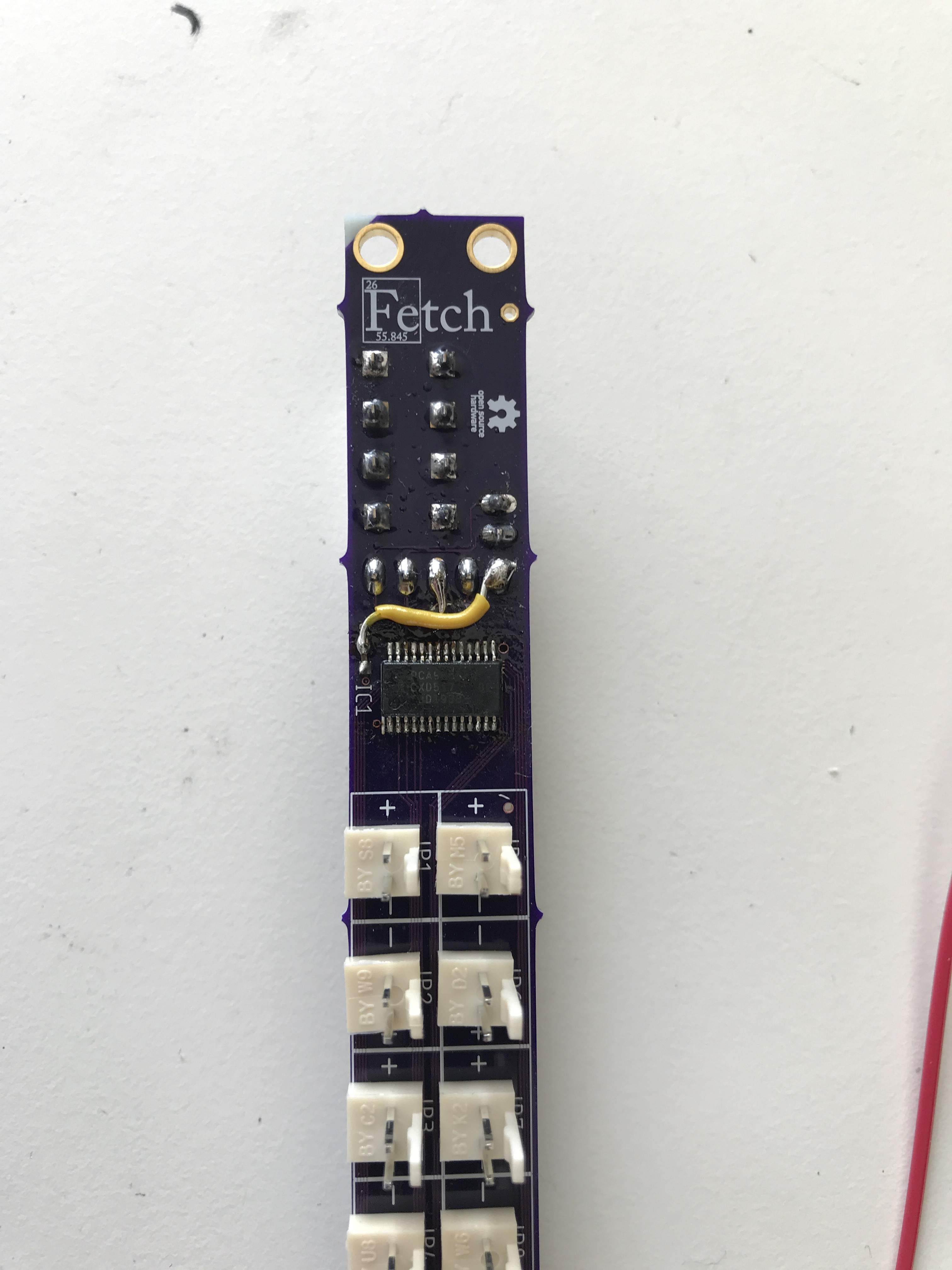
After acknowledging these two roadblocks it became apparent that we didn't really have many ICs to choose from any more. In fact, we could only find a single IC that could provide decent PWM capability at the same time as providing a totem-poled (logic high) signal on an array of outputs: the PCA9685. One IC is enough though! So we could proceed with our "trick" of linking the pulse-width modulated outputs of the PCA9685 to the inputs of an ULN2803 Darlington transistor array.

Integration
When spinning up our first prototype of the new design it quickly became evident that something was wrong. In fact, something was so wrong that a few ICs weren't even connected to power (whoops). But with a bit of bodging we could verify that the PCA to ULN concept worked, and we could then redesign the board and order a full set. This time they actually worked as expected (even though we had a really bad feeling at first due to hooking up some wrong wires). However, as soon as we tried to connect 12 of these boards in parallel with a bunch of jumper wires within a tight enclosure, more problems arose. One of them was easy to fix: broken jumper wires. Another one was worse: broken PCBs (we're still not sure if the PCB itself has broken in some way or if the components on it has suffered too much heat due to poor soldering - it could even be both for all we know). The way we fixed this was by repurposing some of the boards that were currently not in use (the top and bottom rows of the electromagnet matrix are too far away from ferrofluid to be useful with our current ferrofluid tank). This "solution" will probably come back to bite us in the future. Aaaanyway: we also found that the jumper wires added a lot of stray capacitance on the I2C bus. None of us had really worked much with the I2C bus before, so this took a while to figure out, but in the end (after learning a thing or two about pull-up resistance) we solved the problem by using stronger pull-ups (lower resistance).

Firmware rewrite
So with 10 fully working rows of electromagnets, we could finally start looking at our software again. It had grown quite the beast when we were forced to implement PWM through shift-registers in software, so it was quite pleasing to just chuck most of it in the bin and start over. As a part of this rewrite, we decided to split out some of the code in separate libraries that are all specifically designed for our needs rather than attempting to be very generic. This is just a result of how little time we actually have to work on this project. The main firmware is still to be found in the FerroFetchFirmware repo, but it is now dependent on AprocAnimation and MagnetControllerV2-library. Hopefully this code will be much more readable than our previous solution. We've at least found it much easier to develop new features in this new system than in the old one.
As we're already talking about repositories, the new PCB files can be found in the FetchCADFiles repo, and will be uploaded here as well.

 Applied Procrastination
Discussions
Become a Hackaday.io Member
Create an account to leave a comment. Already have an account? Log In.