Hi everyone,
I'd like to share the SBC expansion backplane that I created to pair with the ZTO-80 SBC v3.2.
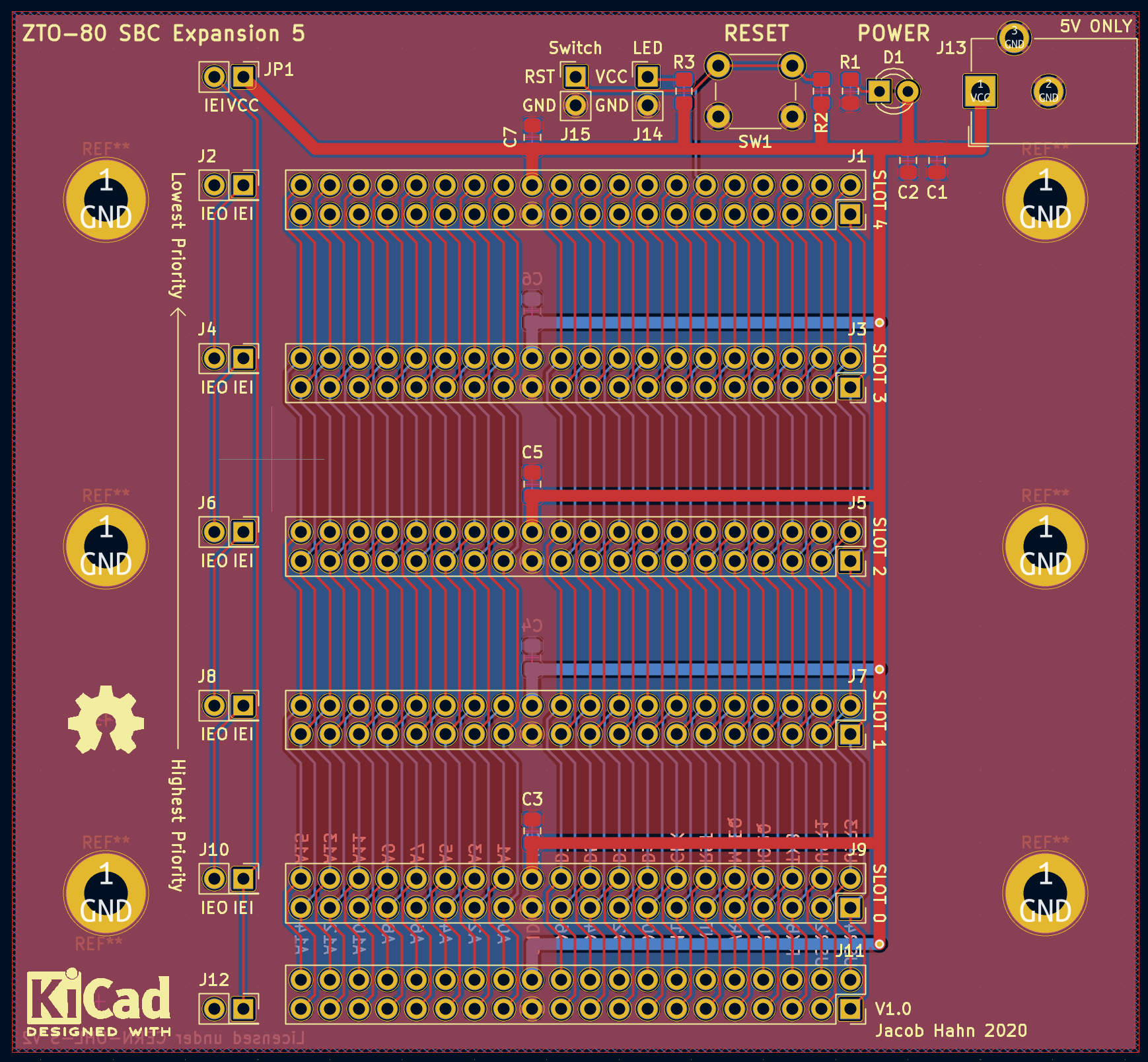
The design is really simple, and in essence is just a modified version of the Modular Backplane. It's fitted with 5 expansion slots, a power input, a power LED, and a reset switch, just like the traditional backplane. However, it also includes pin headers to connect an external reset switch and power LED, along with the most important distinction, which is a horizontal 40-pin female header, allowing the backplane to connect to a ZTO-80 SBC with a horizontal header. It can also be used standalone as a modular system backplane with no SBC attached.
This board will drastically improve the expandability and flexibility of the SBC, combining the aspects of the SBC and the modular system. Using the backplane, new features can be added to the SBC making it as flexible as the modular system, but the backplane can be disconnected and the two can be used separately, keeping the small size and portability of the SBC.
Here's a review of the PCB layout and features of the SBC Expansion Backplane:

The PCB size is the same as the modular system backplane design, at 3.9 inches long and 3.6 inches wide, with five expansion slots spaced 0.6 inches apart from pin to pin (or roughly 0.4 inches from bottom edge to top edge). Each expansion slot is a standard pin header socket with 20x2 pins and 0.1 inch pitch. Six M3-sized mounting holes provide a way to solidly mount the backplane using standoffs. Compared to the original backplane, the power circuitry has been moved above the expansion slots to make room for the SBC interconnect header.
JP1 is a 2-pin jumper which determines how the Z80 interrupt priority line functions. By default it's open, which leaves the priority line floating so it can be controlled by a connected SBC. However, if closed using a jumper block, JP1 connects the IEI pin of expansion slot 0 to +5V, which allows the expansion board to act as as standalone modular backplane. In short, JP1 should be left open if the backplane is used with an SBC and closed if being used standalone.
Like most of the other ZTO-80 boards, power is 5V only and is not regulated on-board. A 5.5mm barrel jack is provided to power the board while it is being used standalone. If an SBC is connected, only have ONE power source connected at a time, either on the SBC or on the backplane, but never both.
As mentioned previously, the SBC expansion backplane can be used standalone. To do this, simply disconnect the SBC, attach your modular system boards, bridge JP1, and apply 5V power through the barrel jack.
While mostly complete, this board has never been produced and was last updated in 2020. Before publishing it to the GitHub repository, I plan on making a some changes to the board to address some design concerns I noticed. I'm not exactly sure what these changes will be or how major they will be, but I'm going to hold onto the design files until I implement those changes. If you have any suggestions on how I could improve this board, please comment them below!
Right now, my main focus is getting this board and SBC v3.2 fully ready, then I'll move on to updating all of the modular system boards and finally beginning the ZTO-80 CP/M design. Thanks for reading!
 Jacob Hahn
Discussions
Become a Hackaday.io Member
Create an account to leave a comment. Already have an account? Log In.
Great project! It would be super great to have a similar backplane with some simple regulation and few power supply options (barrel, pins, etc.), maybe even with battery option! Having +12V onboard would allow EPROM program cards to work easily, and/or Am9511 co-processor.
Are you sure? yes | no