 Dominik Meffert
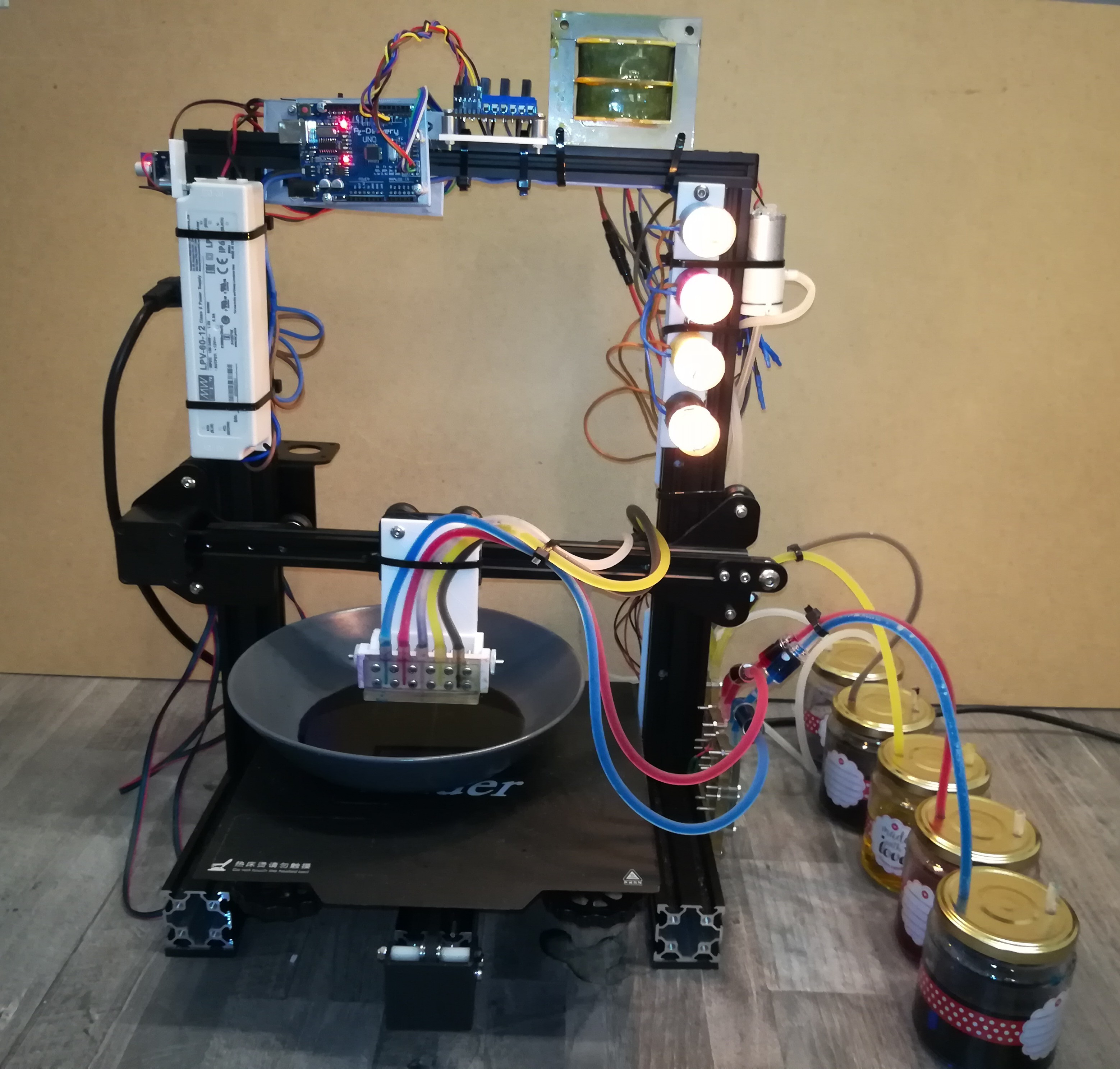
To improve the reliability of the printer I build another printer design that is based on the piezo pumps. The new design does no longer need a level block and ink cycle because the piezo pumps are powerful enough to pump the ink up to the printhead to eject ink in continuous streams or pulsed drops.
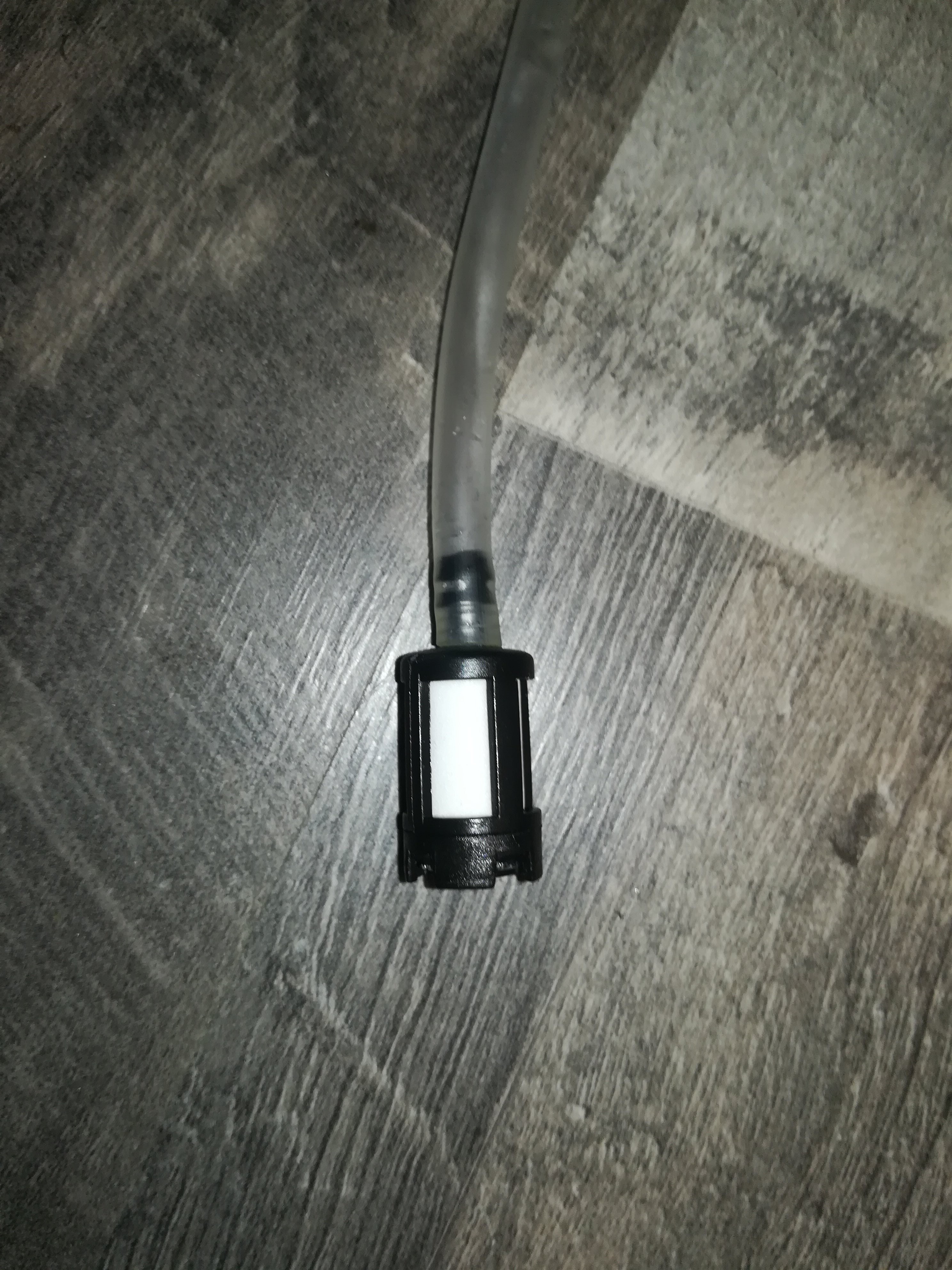
The pumps are connected to check valves and 6mm silicone tubing and they have a smaller gazoline filter at the tube input to replace the large inline gazoline filters.
There is also no longer a piezo disc required in the printhead to eject ink, so that the printhead can be build more compact.
The printhead can be rotated to change the drops' flight parth. It's no longer aligned straight to the bottom but rather aligned at an angle to collect and suck in excess ink with vacuum that in some cases could form a drop that would then drop on the paper.
Included in the SLA printed printhead are channels that guide the ink to the bottom and then again to the top, so that the nozzle is at the highest point on top of a small chamber to prevent it from sucking in air bubbles what would lead to ejecting bubbles from the nozzle instead of ink drops.
On top of the printhead is a SLA printed plate in which I drilled small holes per hand. This plate can also be laser cut or cnc milled to create even smaller nozzle holes.
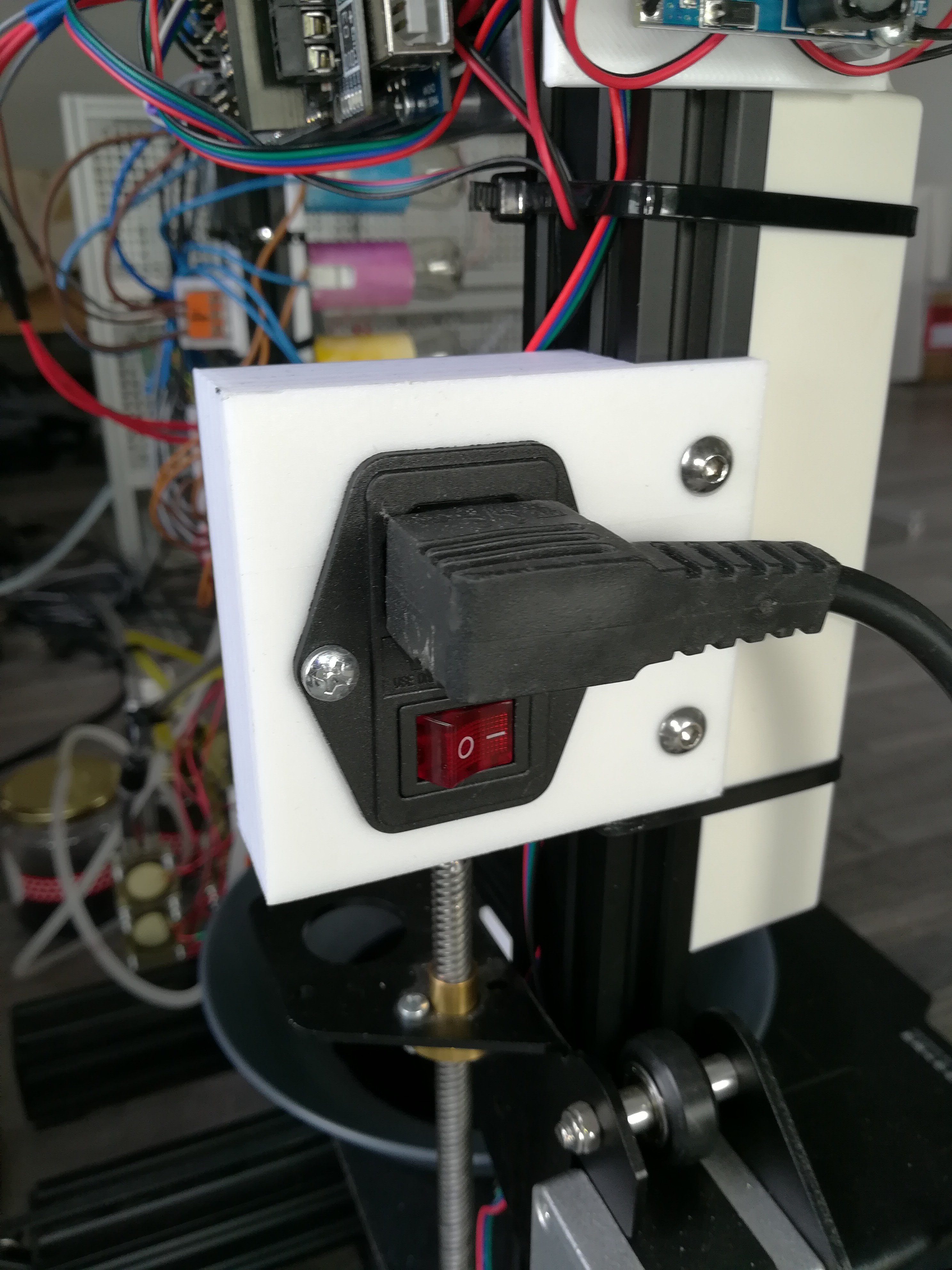
In terms of the electronics I also changed some things. The printer now has a 230VAC IEC input
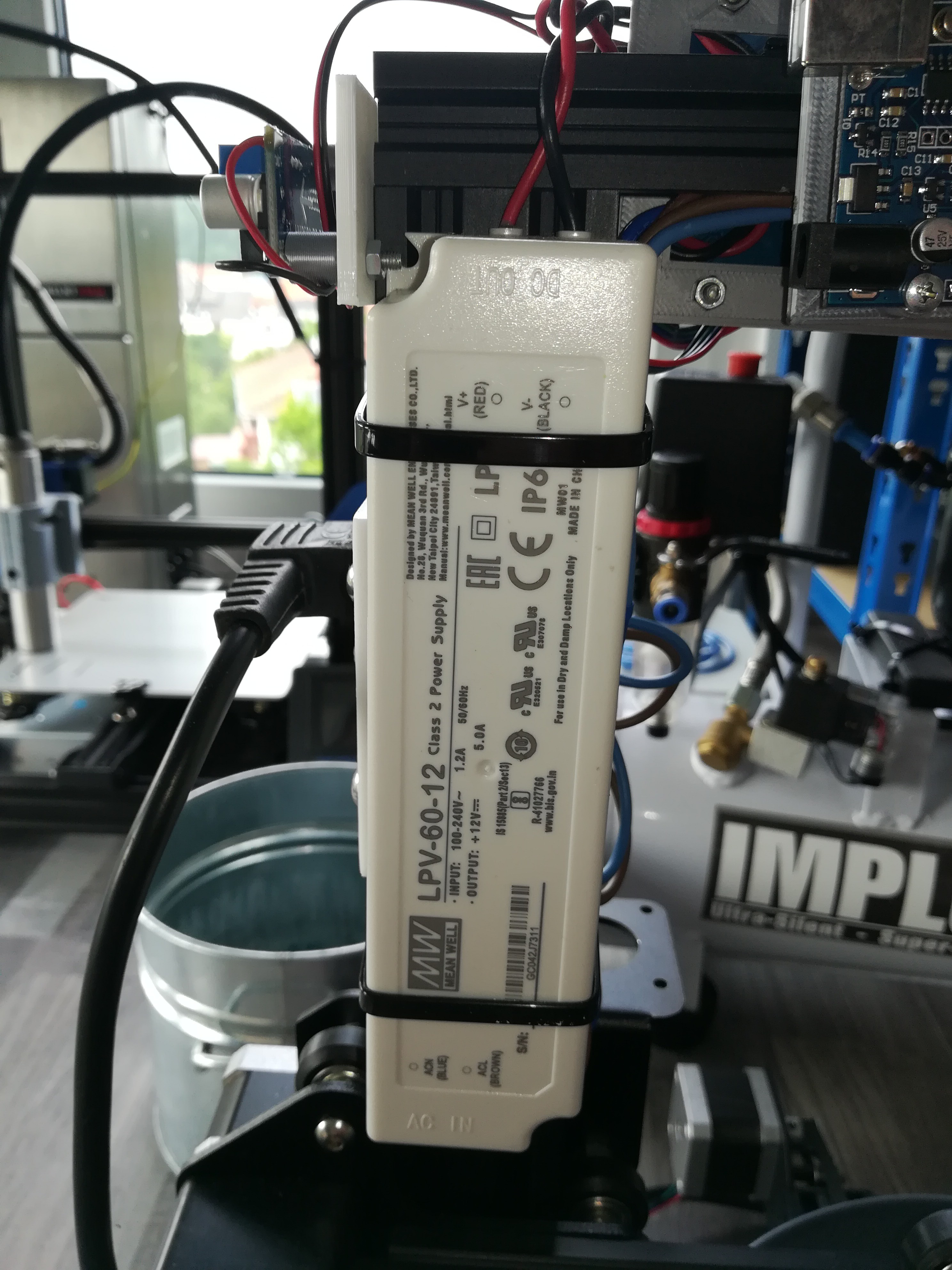
that powers an 12VDC power supply for the RAMPS and
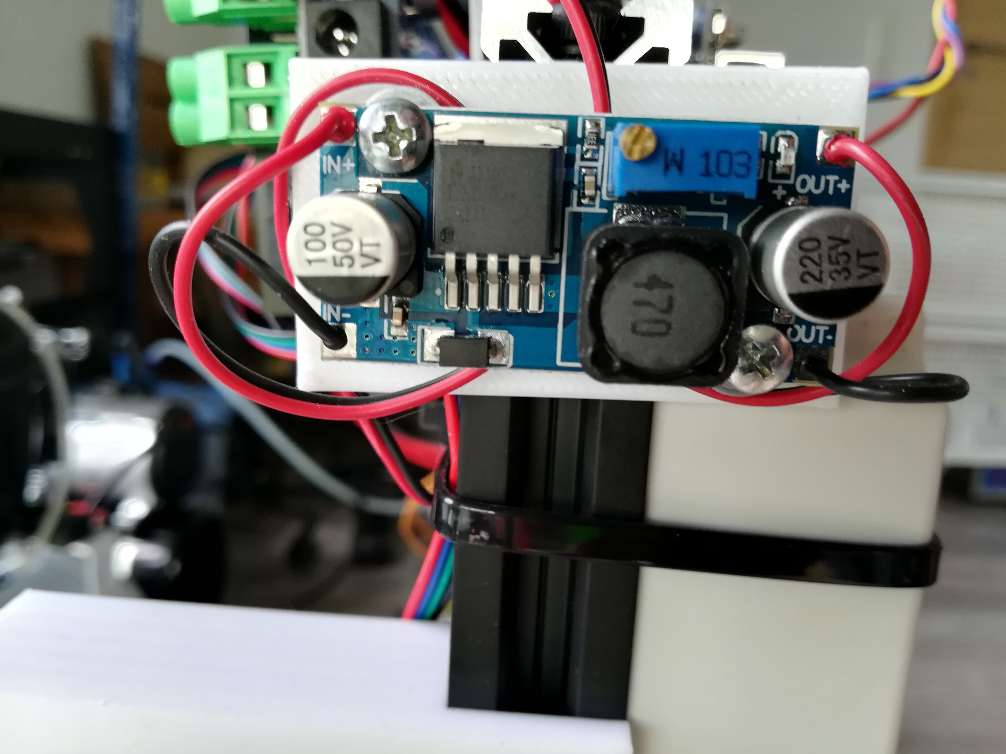
a small step down converter
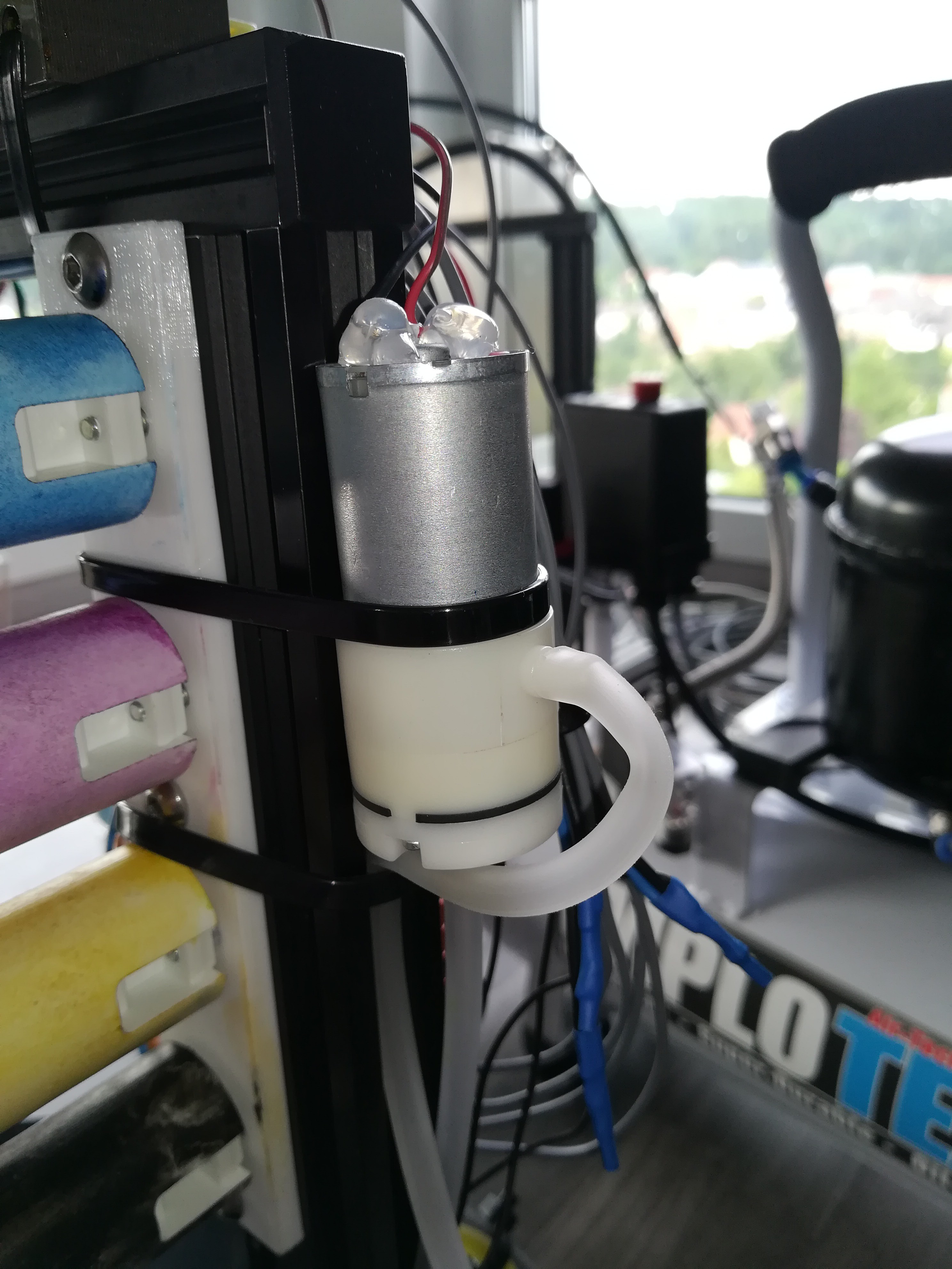
that powers a small vacuum pump with a low voltage (set the voltage that flow rate and noise level is comfortable) which guides excess ink to a container.
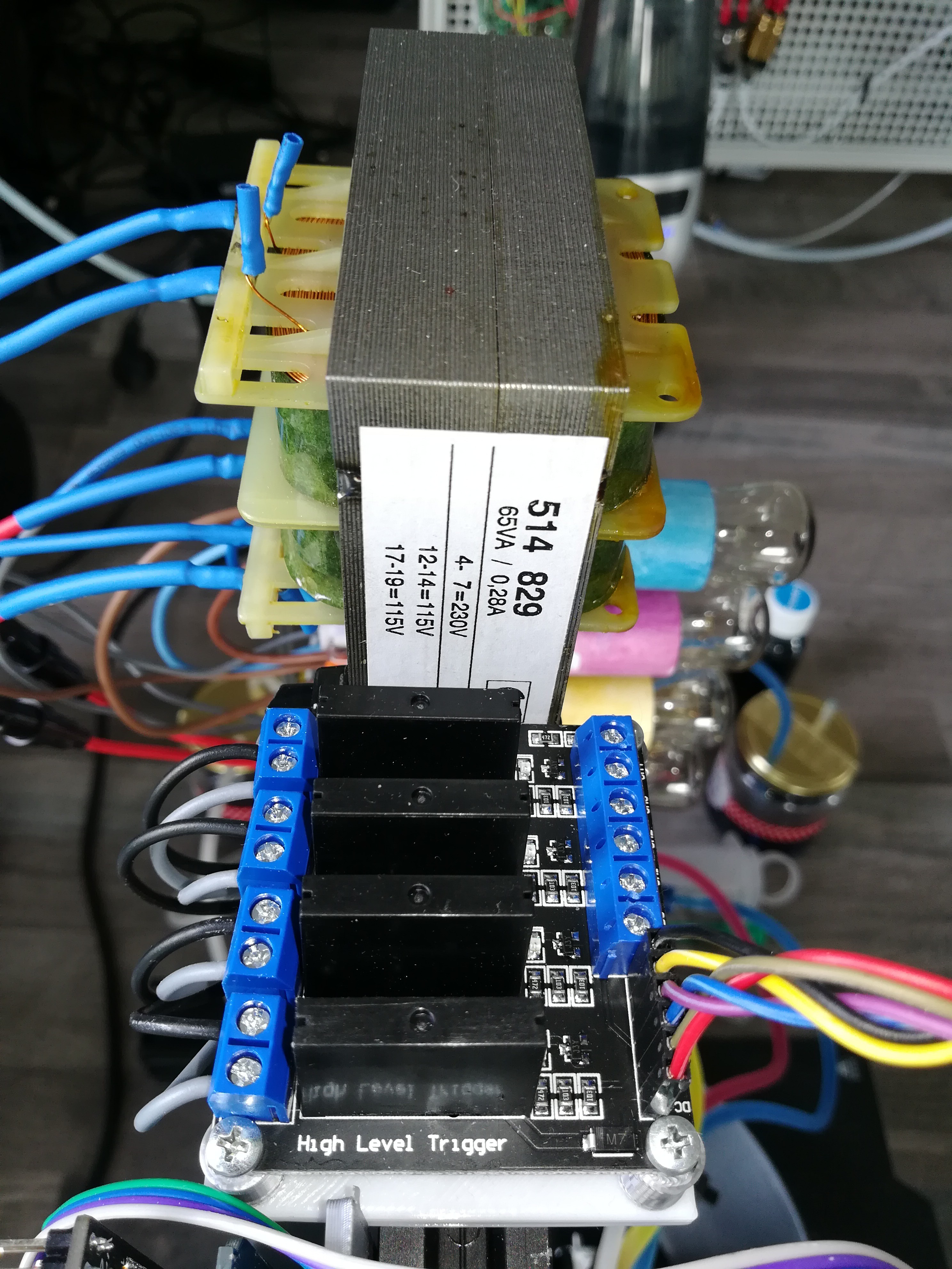
The 230VAC also powers a small transformer that transforms 230V to 2x 115V (In reality I measured 131VAC at the output without a load).
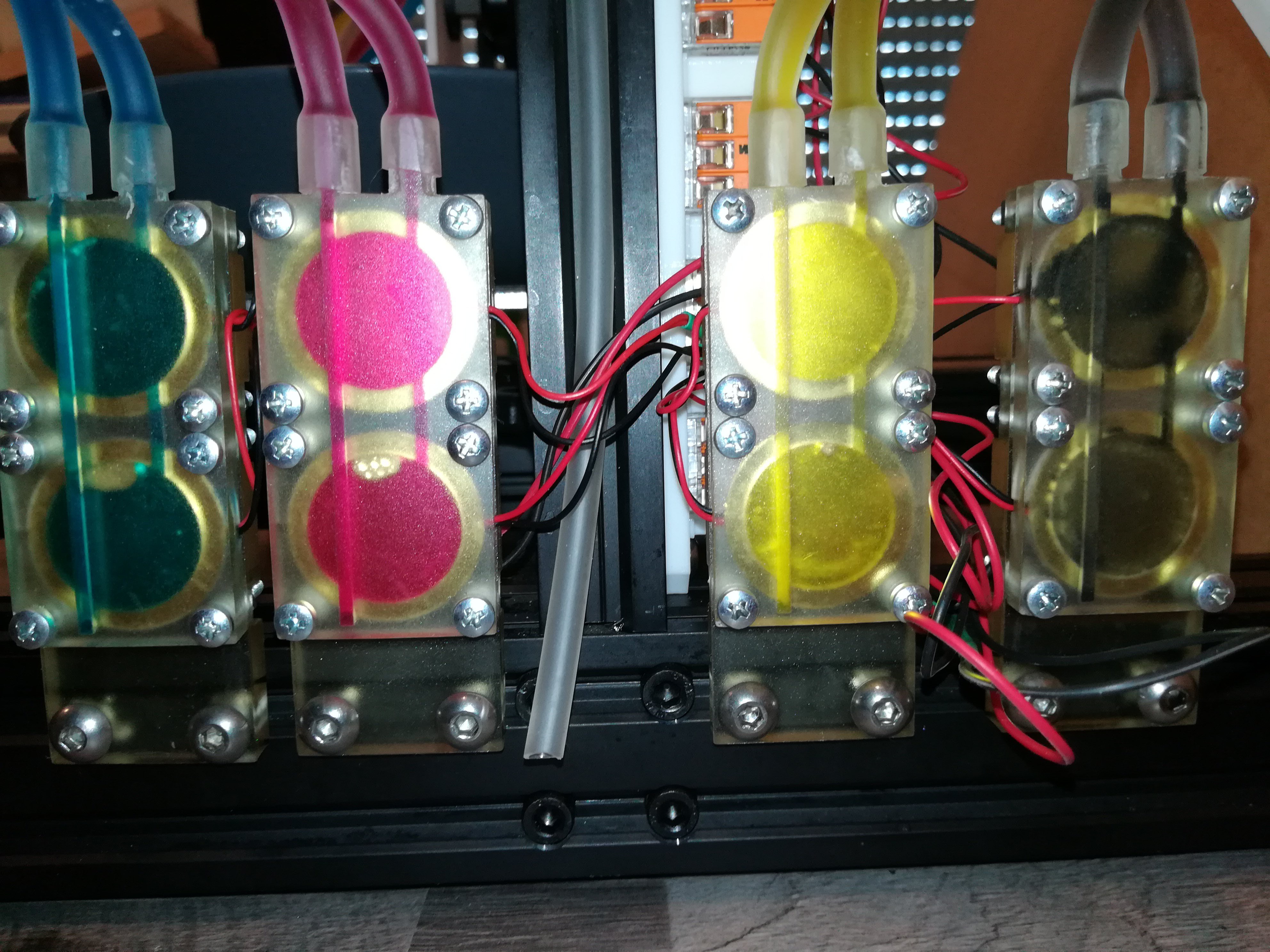
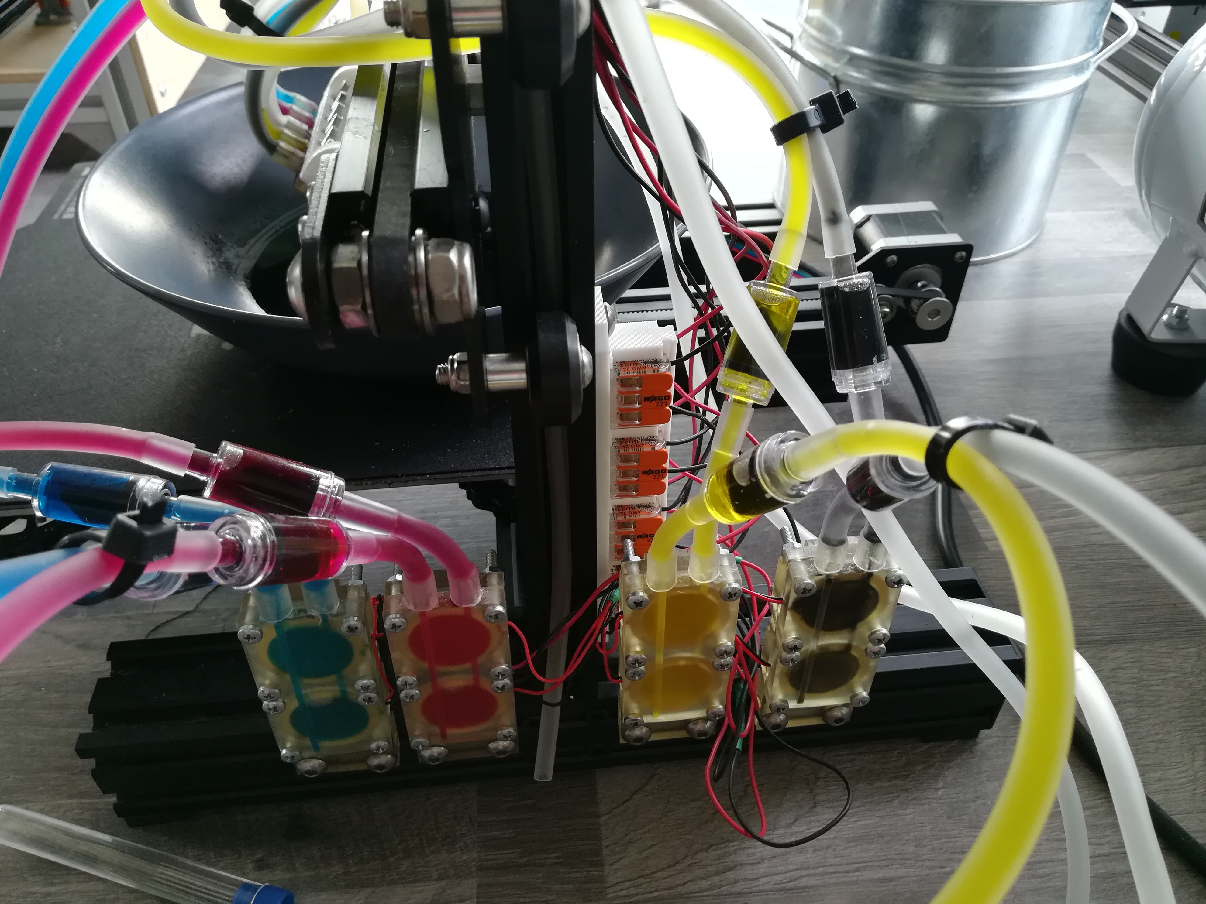
The transformer's output is connected to a 4 channel SSR which switches the piezo pumps.
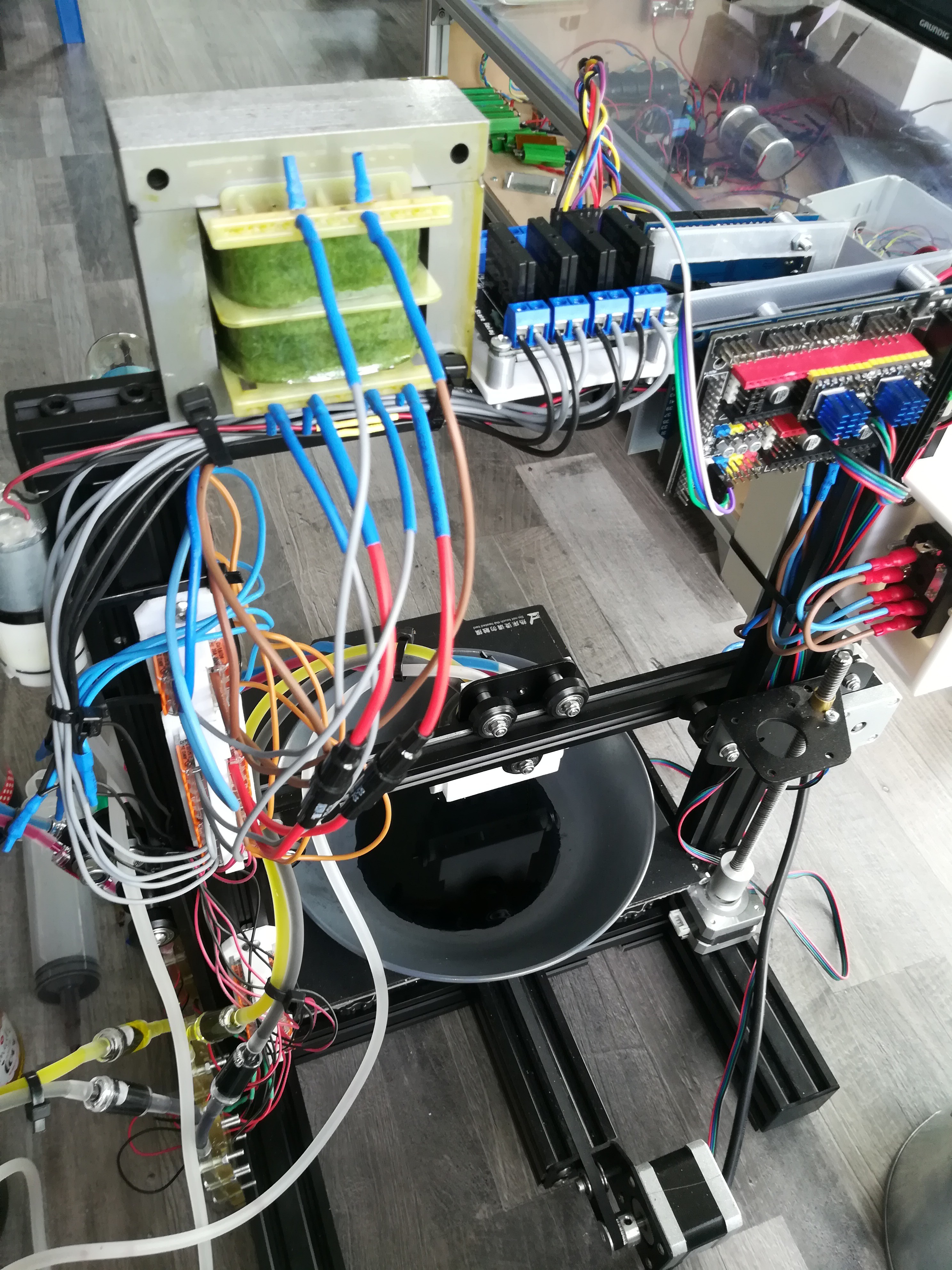
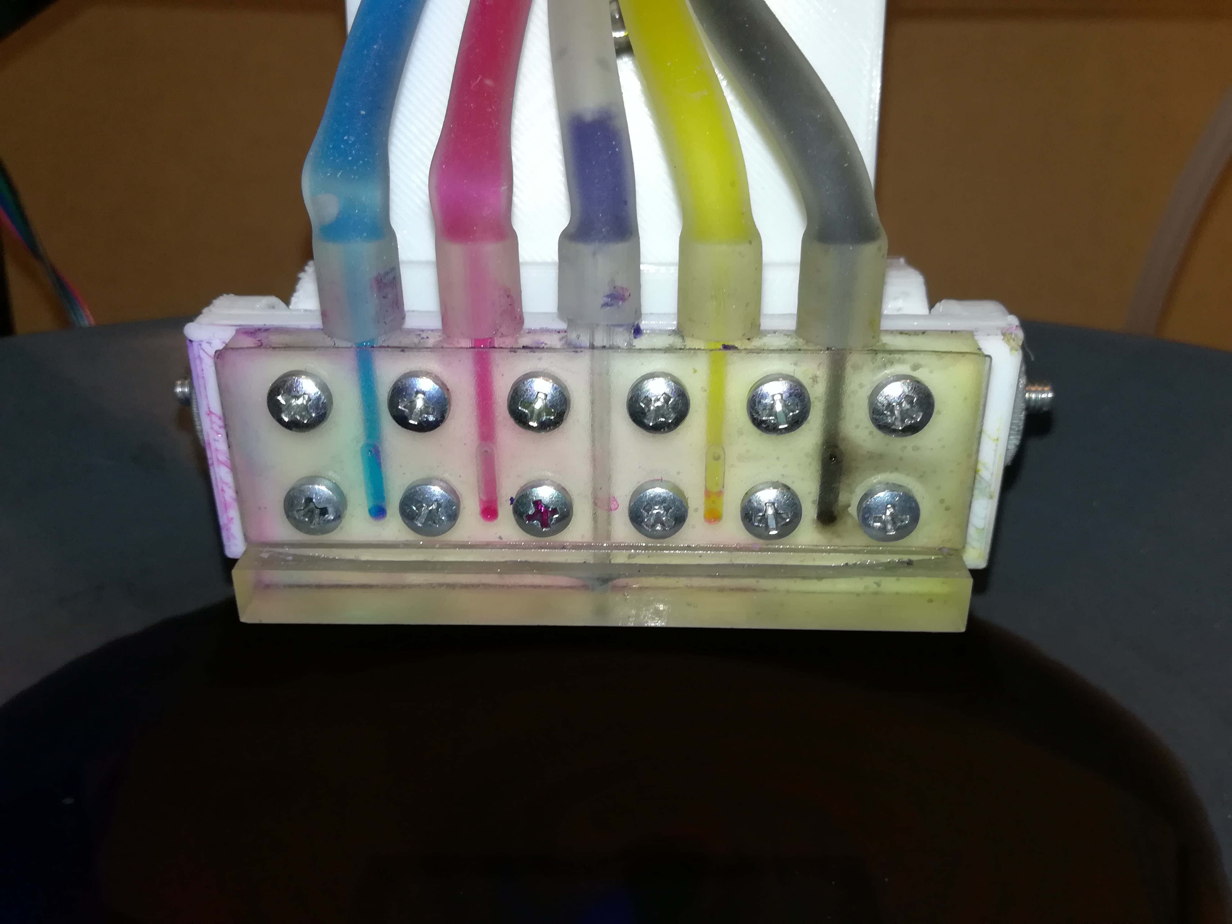
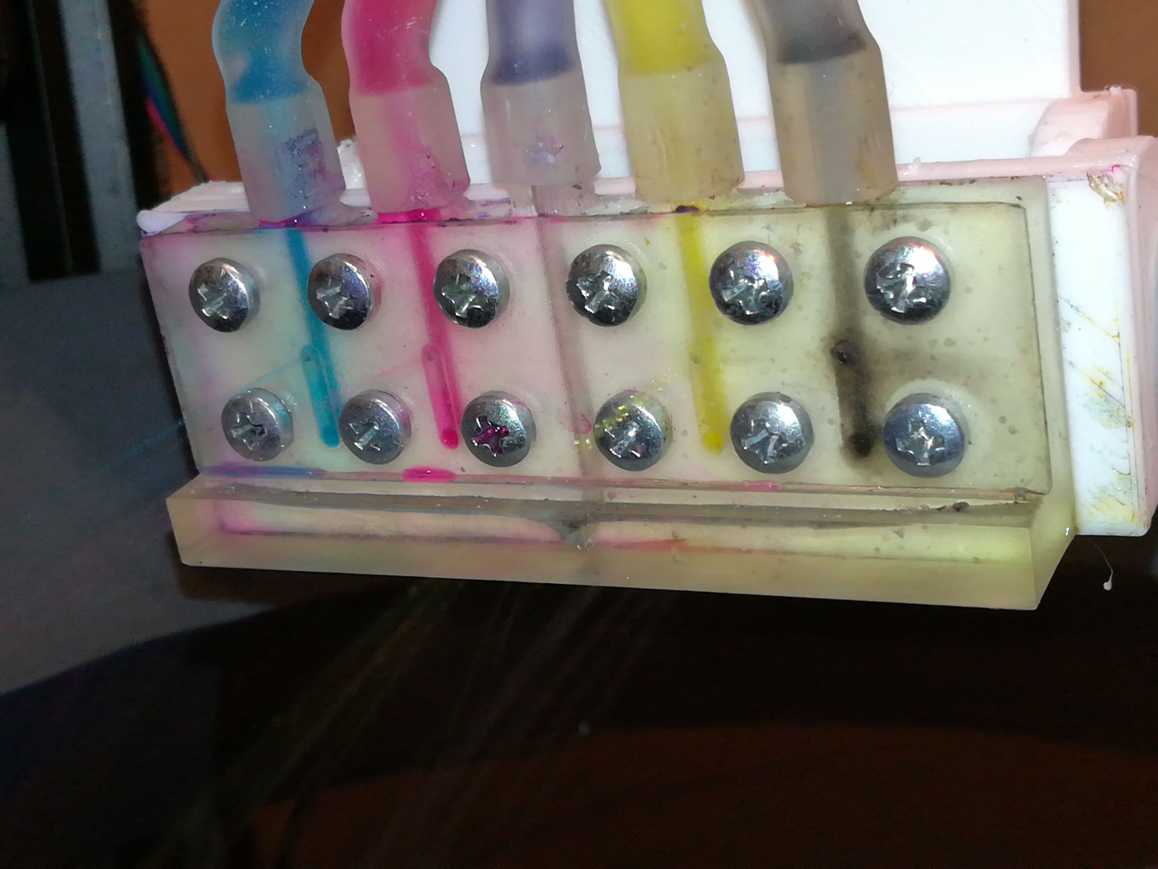
wiring
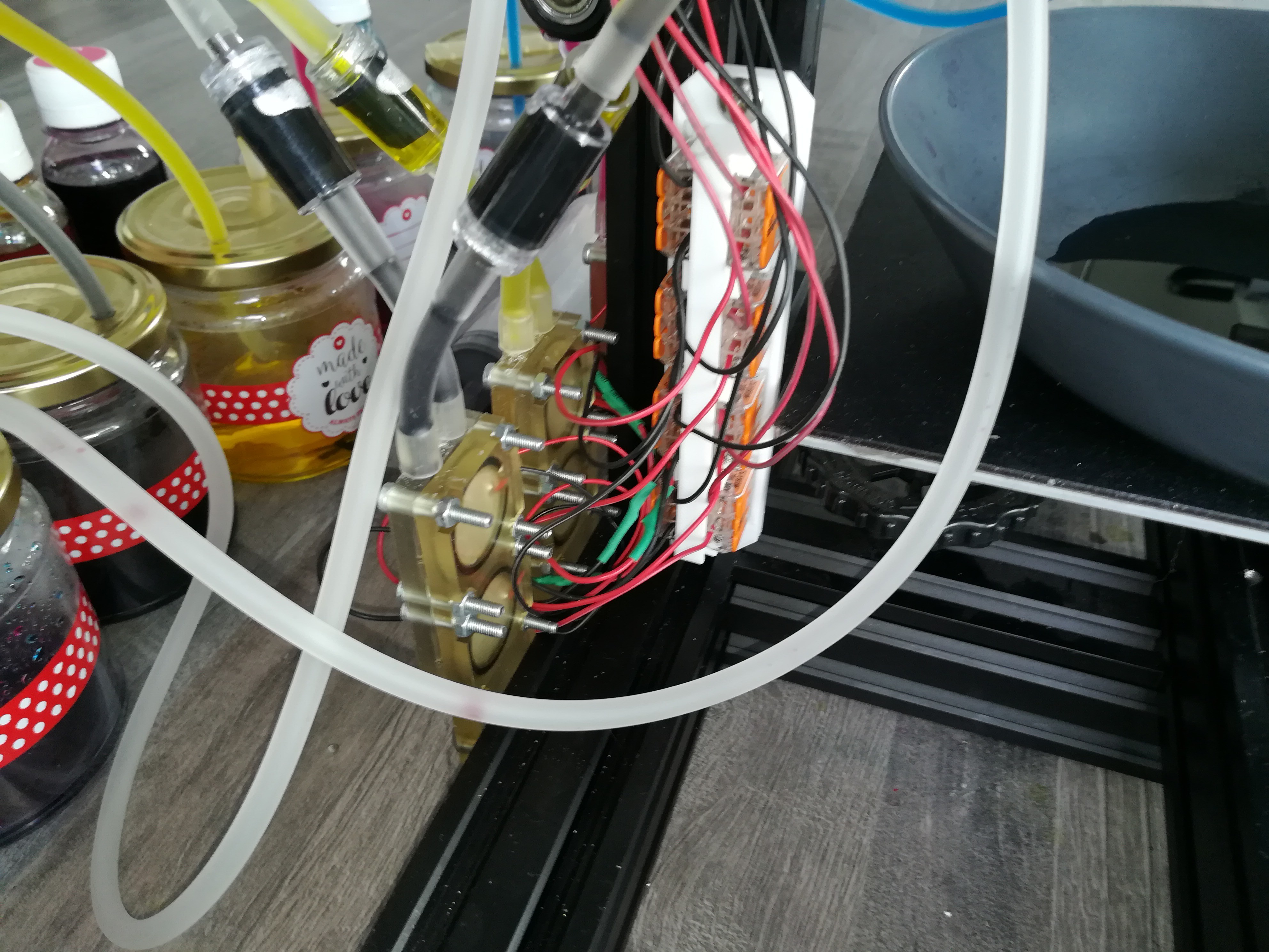
The connections are distributed via WAGO terminals. The backside of the piezo pumps are also printed in transparent SLA resin to make sure that every part sits on the right position and there is no ink leaking what would short out and destroy the piezo disc.
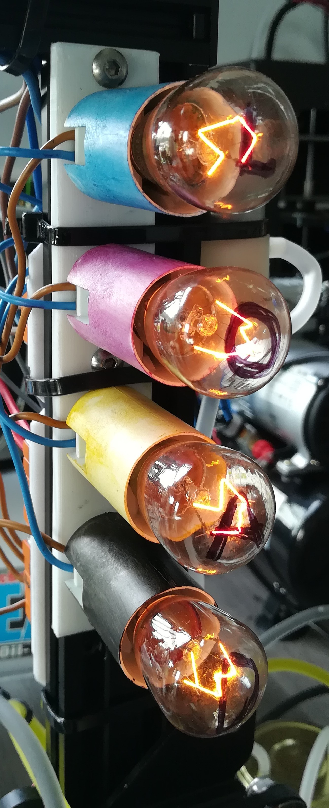
A part of the printer that looks likely a bit weird are the lightbulbs on the right which are used as dummy load which is needed to guide the leakage current of the SSRs around the piezos, because otherwise they would not fully turn off even when the SSR is not active and so there would always be a bit of ink leaking out of the nozzle.
They could be replaced by power resistors, but I had not the right value resistors at hand and so I used 15W light bulps.
I think using SSRs for switching the piezo pumps should be the easiest solution, but probably not the most precise in terms of controlling the piezo motion and therefore the exact amount of ink, but if it would work with the SSRs I will likely keep them to keep the build simple and easy to rebuild.
So, here is the new design and I hope it will be more reliable, because I fixed some problems that I had with the old design.
Discussions
Become a Hackaday.io Member
Create an account to leave a comment. Already have an account? Log In.