 Cirmall
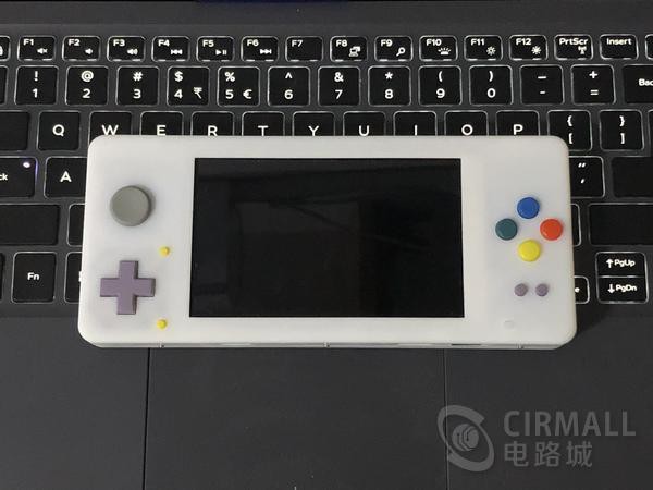
The performance of the retro handheld game console in current market is not so good, few of them are qualified to fluently run PS1 games. The performance of CM3L Computer Book of Raspberry Pi can not only fluently simulate PS1, but also can simulate NDS, DC and PSP etc. In addition, the volume of CM3L of Raspberry Pi is immensely smaller than 3B of Raspberry Pi, so more battery capacity can be equipped while the handheld game console is made portable.
This handheld game console is a Raspberry Pi handheld game console with the CM3L computer book of Raspberry Pi as the core, which supports games on gb, gbc, gba, nds, psp, nes, snes, md, ps1, dc, dos Arcade and other major platforms.
The major characteristics of hardware are as follow:
①4.3” 800*480 IPS screen is adopted, the viewing angle is wide, and the display is fine and smooth, which is fit for the point-to-point display of all kinds of simulators.
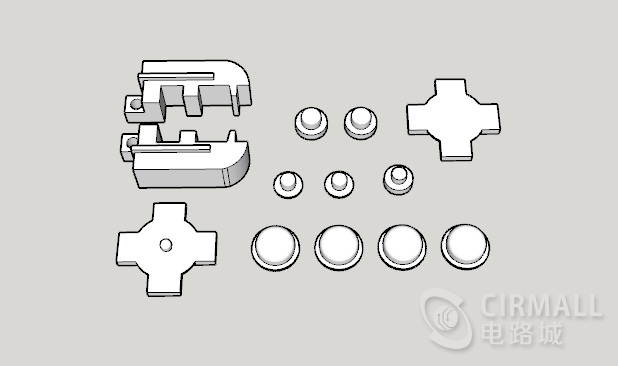
②The same style joystick of 3DS and the same style silicone pad of NDSI are adopted to ensure the hand feeling of buttons.
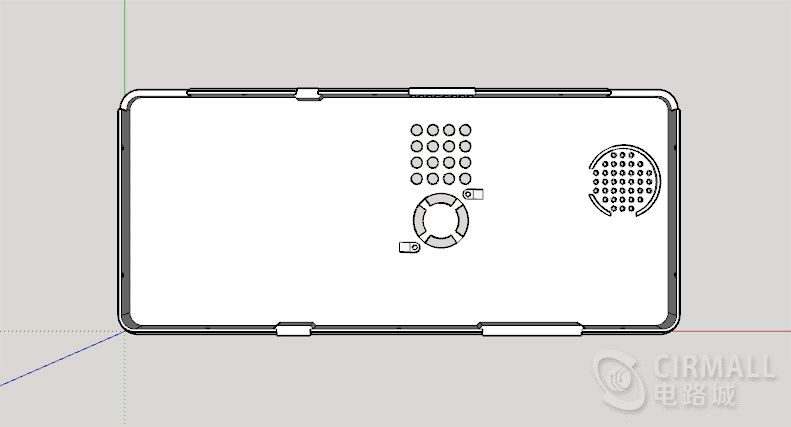
③Cooling fin and micro turbofan are used for CPU thermal dissipation to ensure that the work frequency of the CPU would not be reduced because of high temperature and then ensure the performance and stability.
④The mainboard is separated with button board, they are connected with each other through flat ribbon cable, which is convenient to repair and change buttons if they are damaged.
The major characteristics of software are as follow:
① It is based on 4.4 version of retropie system.
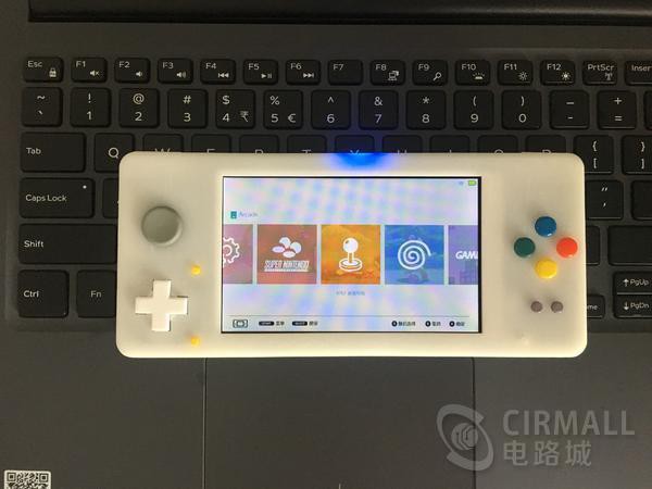
②The relevant operation interface is Chinesized including the front end of ES and the simulator interface of retroarch.
③It joined in the steamlink and can play steam game through streaming with PC.
④It joined kodi player and can watch live and video.
⑤The signal strength of WIFI and battery level are shown in real time on the top right corner of the screen.
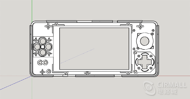
Description of Enclosure Design:
Because the size of screen determined that we have to use the screen of 4.3”, the size of enclosure is mostly based on the reference of handheld game console PSP with same screen size. The final size that we designed is also as same as that of PSP. Because the buttons, button holes and various interfaces on the enclosure are all required to be controlled in precision, the enclosure is produced through SLA 3D printing. The software used is the SketchUp of Google which is easy to use and suitable for people who did not know about 3D graphic design.
It is mainly completed depending on the FDM 3D printer in my home during the early designing period, and then printed the SLA 3D enclosure at cloud factory after it is finalized in later period. Thus, I can save some money on 3D printing during the early period when I have to revise the size frequently.
One of the biggest troubles in design was the thickness of the keys, the thickness difference of 0.1mm varies greatly in hand feel, fortunately, I finally find a relatively appropriate key thickness to ensure the key feel.
Description of Circuit Design:
The software I used to develop is AltiumDesigner. The circuit is mainly built with Raspberry Pi CM3L as the core. Raspberry Pi CM3L brings out a relevant interface for the board card with DDR2 interface, but no power supply, WIFI and Bluetooth functions are provided. Bluntly, it is a Raspberry Pi 3B without power management chip, WIFI chip, Ethernet chip, and Bluetooth chip. In addition to the incomplete peripheral, the performance is just as same as that of Raspberry Pi 3B.
Here below is the topological graph of mainboard circuit:
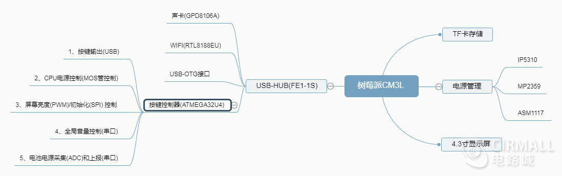
Raspberry Pi CM3L module is connected to the screen by DPI bus (RGB888 model). Because the DPI bus occupied a lot of IO ports, sound card, WIFI and button controller are all connected to the Raspberry Pi CM3L through a four ports USB-HUB, make a USB-OTG interface using the empty USB port, which is convenient to connect to keyboard to conduct the system debugging
In the picture we can see that the button controller is responsible for many functions, the chip used is ATMEGA32U4, frankly, it is Arduino, the third party gamepad library of which helped me save a lot of time for the development. Here we do not talk about it too much, the detailed description will be stated in software part.
The power management chip used is IP5310, a portable power management chip, the maximum 5V/2.1A for charging and 5V/3A for discharging, synchronous charging and discharging is available and the battery level is displayed by 4LED. A discharge power of 15W is more than sufficient to cope with such an electricity-eating tiger, Raspberry Pi CM3L. The only weakness is that the chip is a single inductance solution, pulling out the charging cable when it is charging will lead to a short power interruption of the system, so we must shutdown to assure of the data safety before pulling out the charging cable.
Notes of mainboard design:
The design of mainboard is fairly simple because there is no bus with extreme speed.
①TF card bus should be as short as possible, and the wiring should be at the same layer.
②DBI bus should be routed in a separated single area without any interference from other buses. Here I didn’t make the equal length, but has via hole, it is still very stable.
③The WIFI antenna is placed at the margin of the board, do not make copper covered at antenna area.
④Large current power line should be as wide as possible to ensure the stability of the power supply.

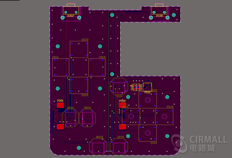
Notes of button board design:
It does not need to talk too much about button board, the only thing we must pay attention to is the locating place of button which shall match the enclosure. What I did was to generate a flat CAD file from the enclosure file, then I transfer the CAD file with coordinates into the PCB file to locate the position of each key.
After the PCB drawing is completed, it can be sent to the PCB board factory for proofing. Here I made samples in Jialichuang, and we can also post some common capacitive resistance devices if we ask for SMT service, which is convenient for subsequent welding and debugging.
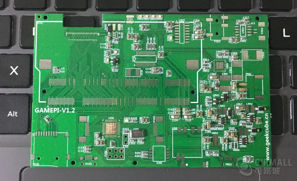
It can be seen that most of the capacitive resistors have been installed, and the remaining interface and IC need to be welded by ourselves.
Since it has been adjusted before, we can start to assemble after the welding is completed. As the assembly of many parts is also a heavy work, it takes about an hour to assemble one.
①First, put the key and silicone pad in the corresponding key hole position on the top shell, and then put the key circuit board on the top and fix it with screws.
②Then we need to put the LCD board in the middle of the top shell and fix it with screws.
③Connect the mainboard and button board with two 12P flat cables.
④Insert the CM3L module into the mainboard and attach the radiator fin to the CPU of the CM3L module.
⑤Fix the battery to the bottom left corner of the chassis with double-sided adhesive tape, fix the fan to the corresponding hole position with screws, and fix the speaker to the horn position with hot-melt adhesive.
⑥Finally, we insert the 2P connector of the speaker into the audio interface of the mainboard, and insert the 2P connector of the battery into the battery interface of the mainboard.
After completing the above steps, the interior of the game console is basically assembled, as shown in the following pictures:
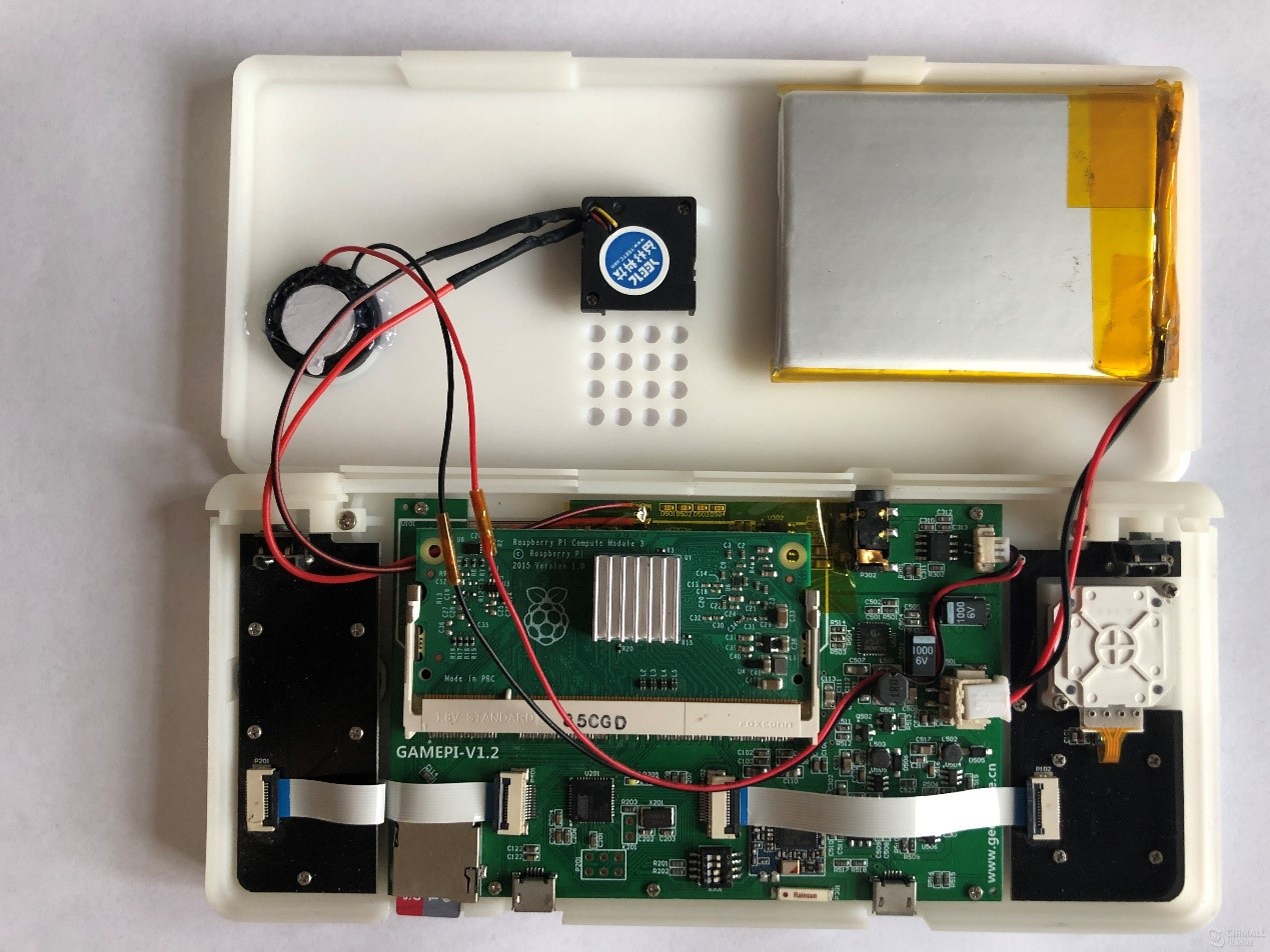
After that, we buckle the bottom enclosure and the bottom enclosure together with the fixed screw on the side, and the hardware part is completed!

Description of Software Development
The software is mainly divided into two parts, one is the embedded program of the key controller (ATMEGA32U4) section, and the other is the scripting program of the retropie system.
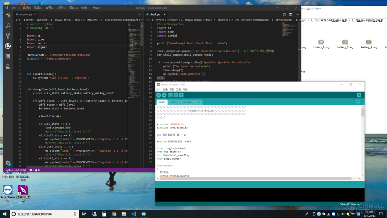
The embedded program in the key controller (ATMEGA32U4) section is written using the Arduino IDE. The board card used is foreigner's Pro Micro, since it is not an official board card, you need to install the USB driver and add the board option of Pro Micro in the Arduino IDE before use. Here are the documents written by foreigners: https://learn.sparkfun.com/tutorials/pro-micro--fio-v3-hookup-guide. After completion, the board card is selected as "SparkFun Pro Micro" and the voltage is selected as "3.3v /8Hz", after which the development can be carried out.
Main functions of the program:
①Make it as a virtual gamepad device via USB port to provide gamepad input to the retropie system.
②Judge whether turn on/off retropie power supply using a combination of buttons.
③Set and initialize the LCD screen through SPI bus, and make it enter DPI working mode (the default mode is mode DBI). When the specified backlight adjustment key combination is detected, adjust the backlight brightness by controlling the LCD backlight chip through outputting PWM square wave.
④When the specified volume adjustment key combination is detected, it will send the specified string command to the system through the virtual serial device of USB interface, and adjust the overall volume with the specified script running on the system.
⑤The current battery voltage is collected by the ADC of the chip, and the current voltage is sent to the system through the virtual serial device of USB interface.
Main functions of Retropie system script:
①After boot, check whether the USB external hardware (WIFI, sound card, handle device, serial device) of the system has been successfully mounted.
②Monitor the instruction information received by the serial port (the instruction sent by the button controller through the virtual serial port), and make corresponding operation (modify the overall volume of the system, change the icon displaying of battery level).
③Monitor whether the current system WIFI is connected, read the current WIFI signal quality, and modify the current WIFI icon displaying.
System Customization and Optimization
Since the native retropie system has an English interface, and many functions are not comprehensive, here we need to optimize and set the original retropie system, including system partition changes, USB device mounting, emulator installation, Chinese interface, script automation, etc. The main purpose is to realize the Chinese UI of the system, real-time display of the system state (WIFI and battery level), and being fool proof that is playable by hand (installation and settings and key mapping of the simulator). The process of customization and optimization is quite tedious. Please refer to the "Tutorial file" for details.

Demo Video:
---- Backlighting and volume adjustment ----
---- Power level and WIFI icon displaying ----
---- Use KODI to watch the live demo ----