 Jon Kunkee
In three sessions of a few hours each, I followed DIYGeiger's excellent instructions to assemble the kits. This post is really about the finished kit, so it has only a little bit about the process.
Here's the GK Plus with the Display Adapter, stacked with full headers:
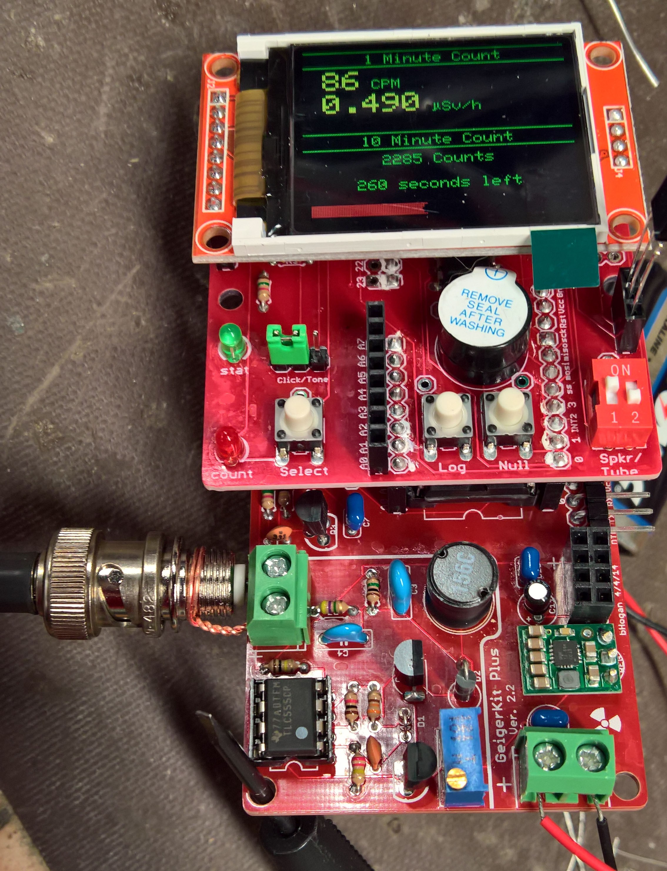
This is not a beginner project, but it was doable with my limited experience. Please don't notice my mistakes, like the fat solder joints on the Pololu regulator (small green board in bottom right) or the obvious water spots where my alcohol-based cleaning wasn't super thorough. :)
With some encouragement from a friend in this makerspace, you can see that I cribbed in a BNC connector and hooked up my Geiger-Muller tube. (The twisted copper bit is his handiwork.)
It didn't work. No clicks.
That's fine, of course; the simple tests the instructions suggested had passed, but my GM tube is rated for 500V and not the as-built 450V--and the kit is only set up to do that, not guaranteed to. I had not actually tried to measure the voltage the board was putting out, so that was the next step.
The first thing I tried was to directly measure it with my multimeter, which as a 10Mohm load is guaranteed to only read about half of the actual voltage. This demonstrated that my meter is actually broken, so my friend pulled a Fluke out of the drawer and we carried on,
I chained the nine 10 Mohm resistors together, alligator-clipped it into the circuit, and set up the multimeter to measure the voltage across the bottom resistor. Using the math for a 9-resistor voltage divider, I set the voltage to ~500V based on that measurement and set the tube back up.
I got clicks! Then it clicked some more. Then it started clicking so much it was nearly a hiss, ignoring the proximity of my sample.
Crap.
My friend had to leave at this point, so I stared at our improvised rigging and wondered if I could simplify the math from a 9-resistor divider to a 10-resistor ladder by using the voltmeter's series resistance as part of the circuit. I looked up the Fluke 115's impedance which is actually kind of hard to find: >10Mohm.
Welp, that makes a nice, clean, 10-resistor 100 Mohm divider, so I hooked it up.
Apparently I had been pumping ~940V through my tube. I hope I didn't hurt it...
With that in place, I then re-set it to ~550V, hooked the tube back up, and, lo and behold, the tube started working! The rate shown in the photo is an accumulation of time both with and without my sample.
Later, thinking about it, I realized that the reason for the massive change was simple: If the meter was 10 Mohm, then the 9-resistor divider was a 10||10+8*10, or 85 Mohm, load, and the voltage I was reading was 5/85 (.05x) of the real value instead of 10/90 (.11x).
Even later I decided to look at the kit instructions again and learned there's yet another problem: even 100 Mohm is a heavy load for the power supply, so it will read ~3/4 of the actual voltage.
I think I'll try a 1 Gohm load before doing much more with the actual tube. Oh well.
Here's the tube itself. All I know is that it came out of medical equipment, works at 500V, has a mica alpha window, has a BNC connector on RG-59 cable, and was sourced off of eBay by my dad:
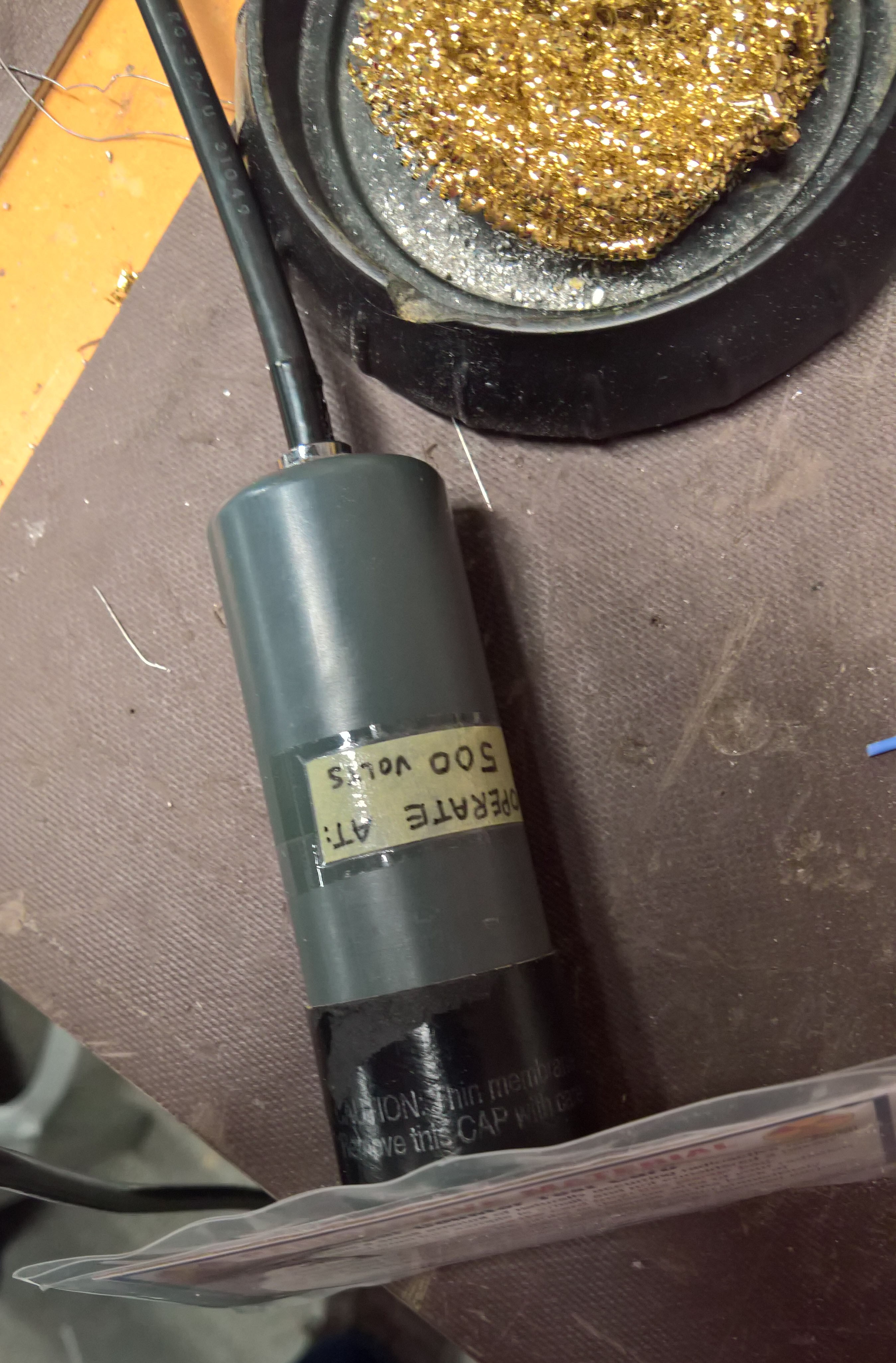
I also now know that it is not supposed to operate at 950V. Math is hard, OK? ;)
It also seems to work OK with the BNC shield at +550V.
Side note about the kit: if you use the Display Adapter board, be sure to install *all* 4 of the longer headers at once (just like the instructions say) following the procedure in the instructions. This makes mating the two boards much easier.
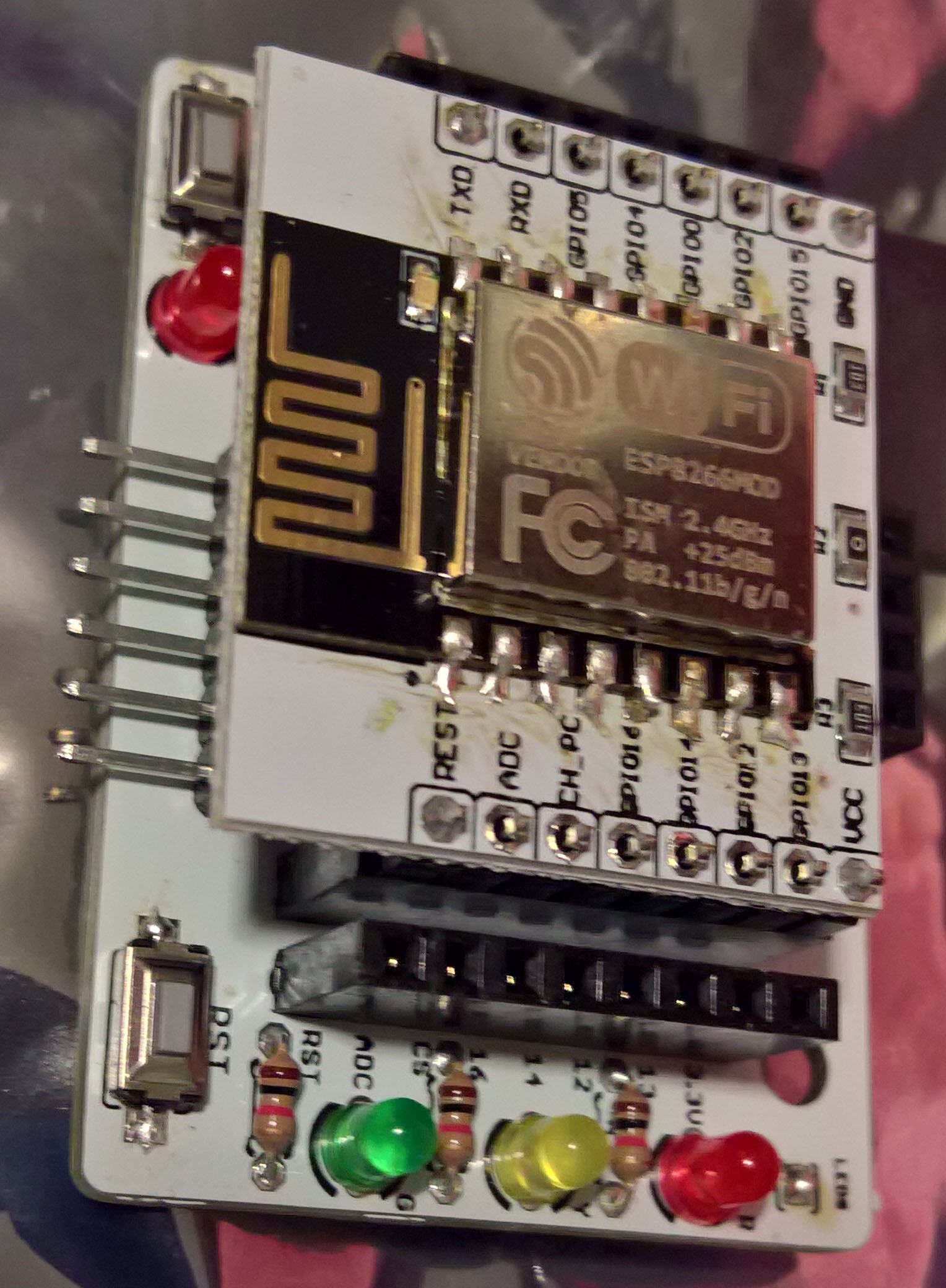
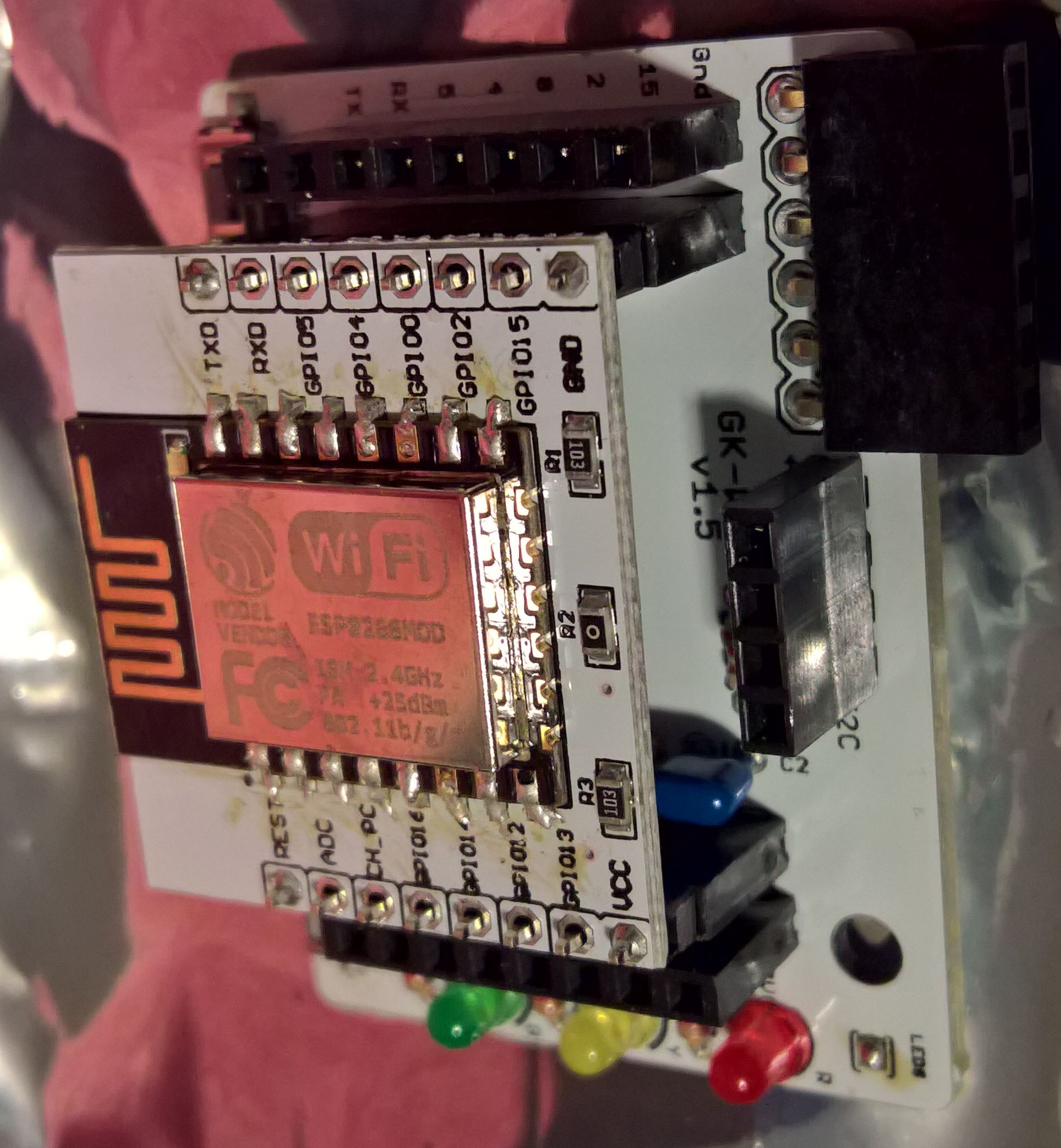
The WiFi kit was quite a bit fiddly to solder; I haven't programmed the ESP8266 yet, so I don't know if the soldering I did on the ESP's module edges actually works.
A short video of the GK Plus + GM tube setup in action with my UnitedNuclear Geiger Counter Test Card:
Discussions
Become a Hackaday.io Member
Create an account to leave a comment. Already have an account? Log In.