With the electronics successfully mounted to the foam board and a good chunk of the programming done, Version 1 is done.
It is now time to face my nemesis, the enclosure, for Version 2.
Some time ago, once I had the larger components figured out, I acquired a Hammond Manufacturing 1591XXESBK project box for this. (This is what provided the outline and size constraints in the v1 mounting post's pictures.) I also found a shiny power button, some nice tactile buttons, and a couple of switches to go with it. A few protoboards, some solid wire, the upcoming long absence of a friend with hand tools know-how, and the motivation of participating in the Hackaday Remoticon got me over the line to start prepping the project to get bolted into a proper home.
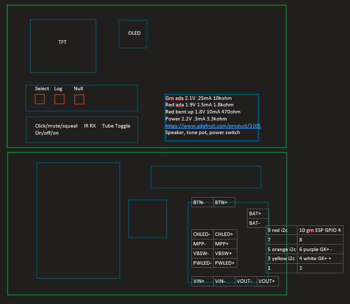
I ruminated a bit about how to fasten circuit boards and screens to the front plate and ended up at "If I can roughly lay out the front-plate elements, I can group them by component height and build up the boards. Once they're securely on boards, my friend can help me figure out mounting."
This started with a sketch in OneNote, where I added notes and boxes as I picked where to put what:
Button Board
The first board was pretty straightforward: a 100-mil header and three buttons:


The only real challenges here were working with the header-end of the wires to make sure nothing shorted. I double-checked the button pin assignments several times, then did a round-robin continuity check after I was done to make sure everything was working.
Switch Board
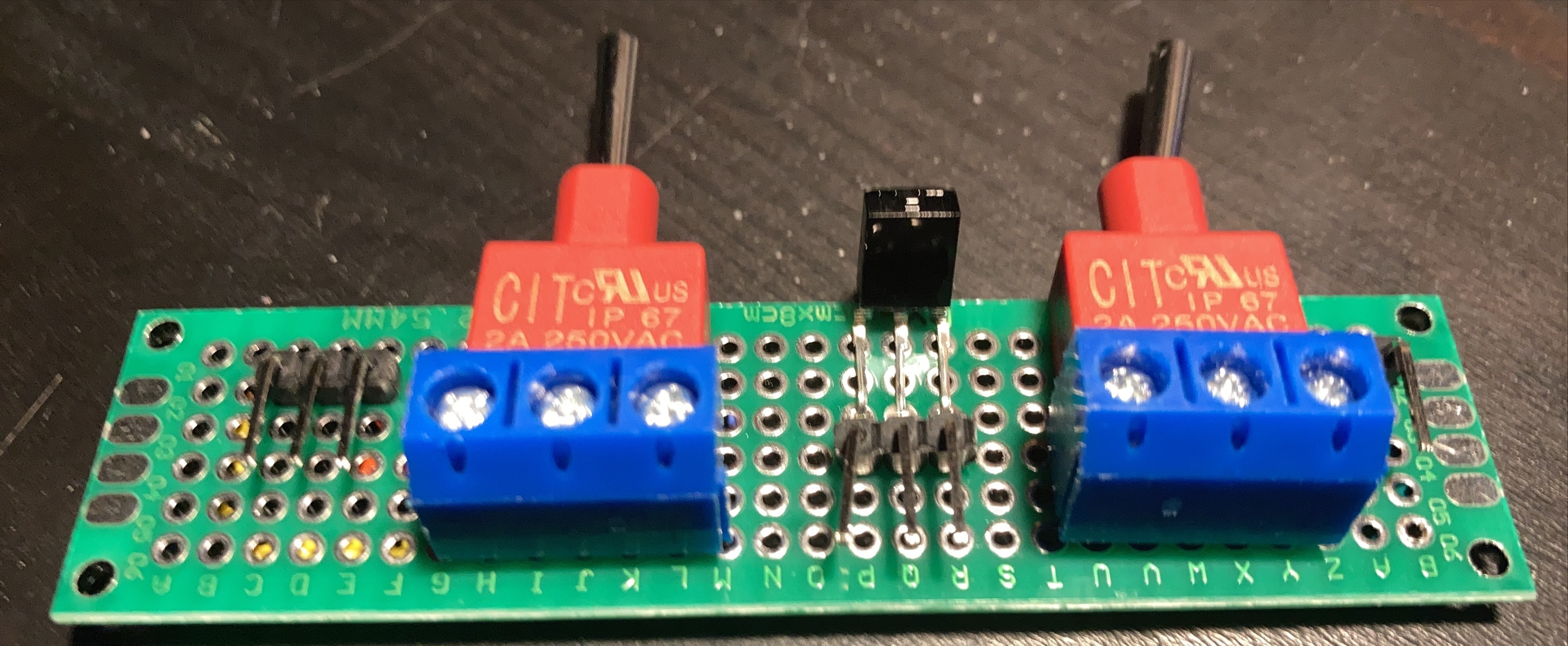
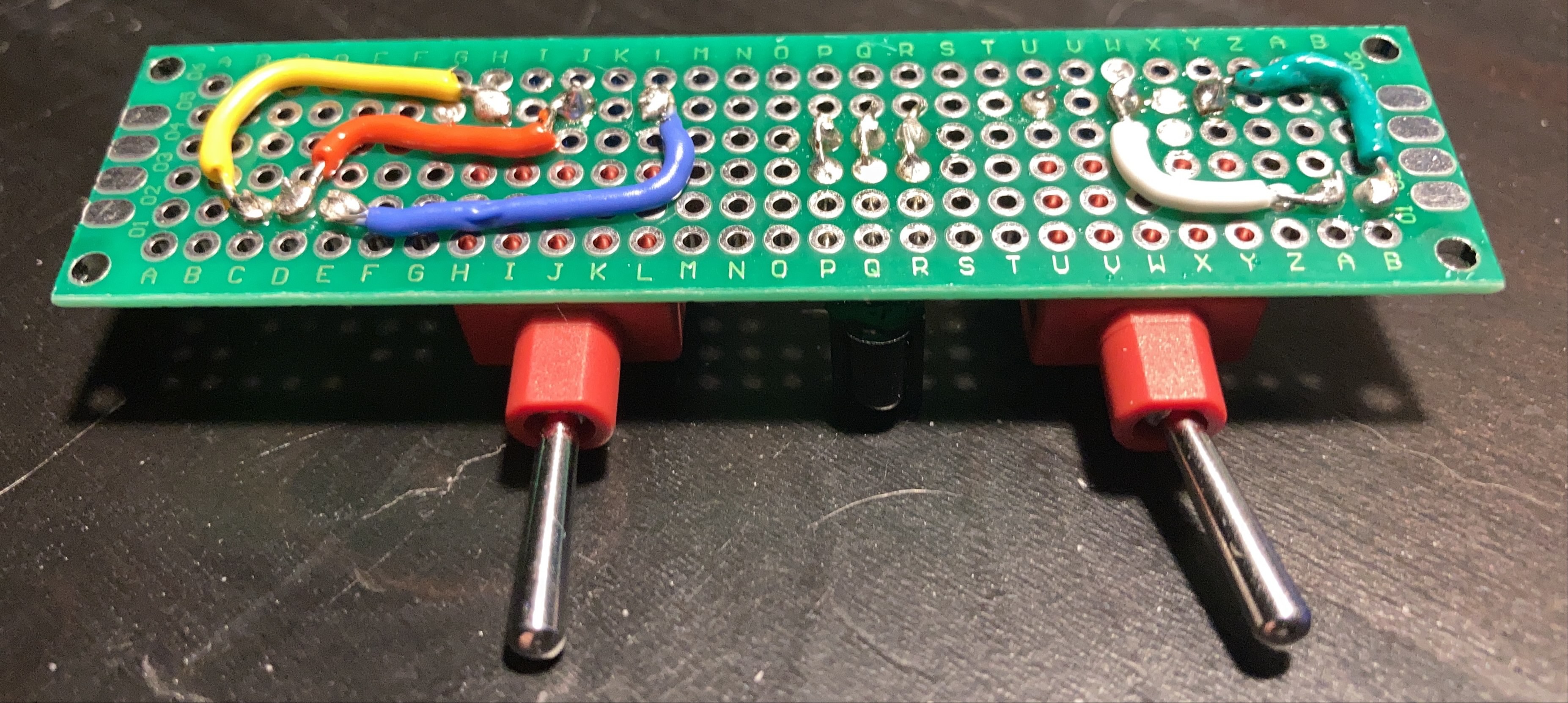
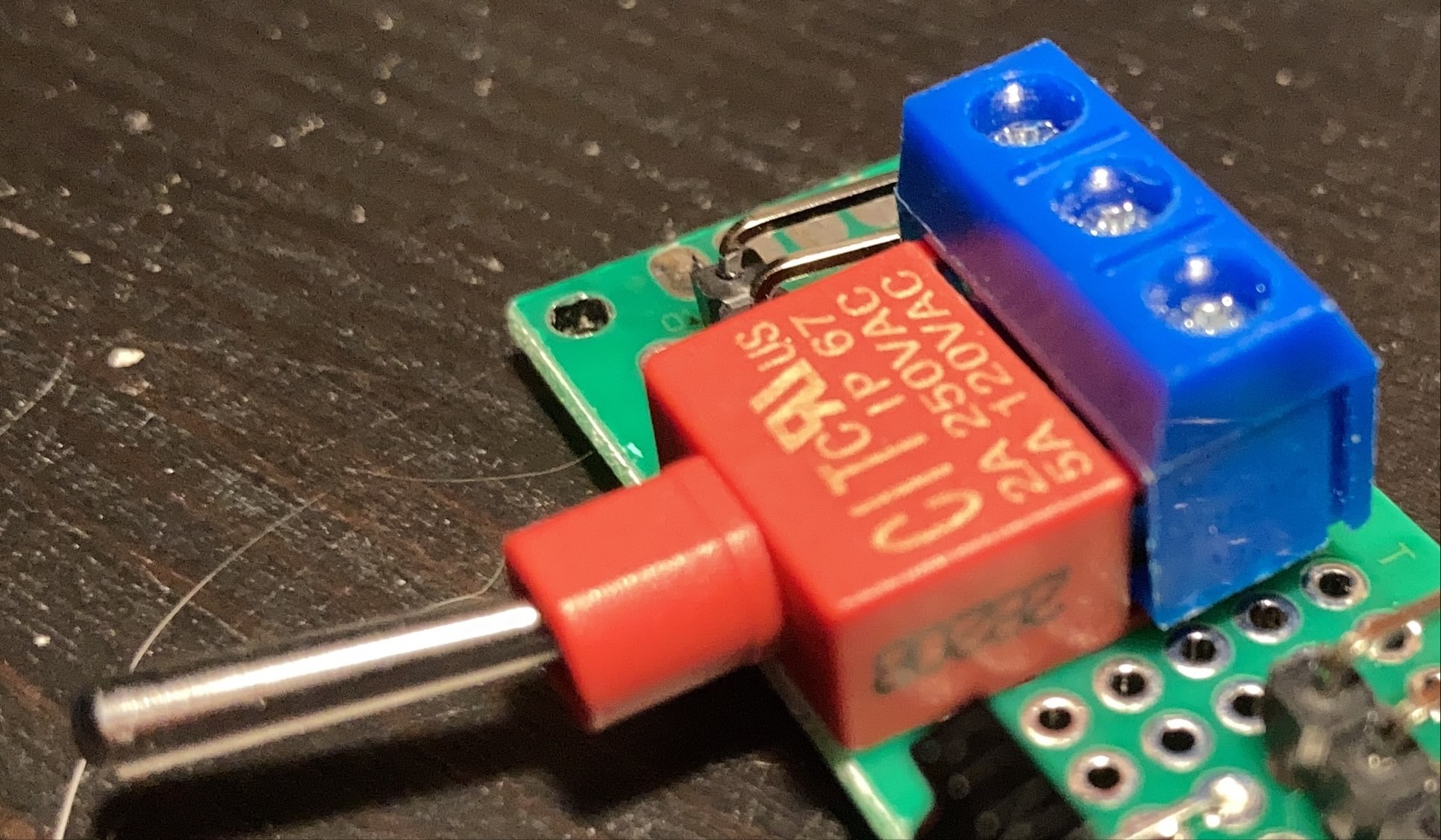
The second board was more challenging. I misread the mechanical drawings of the toggle and on/off/on switches I bought, so the pin spacing was wrong. On top of that, the 250Vx2A-rated leads were too thick to fit through the holes on my board. By happy happenstance I noticed that some wire terminals I had incidentally acquired (in a bundle with the perf board) were 100-mil spaced and the switch pins fit into the screw-down terminals. I'm not sure how I'll attach the resulting combination to the front plate, but it works and provides a nice place to mount the IR receiver:
Oh, and in case you're wondering about the excessive free fiber content in these pictures, they were project contributions of a feline variety.
LED et al. Board
Once that was done, it was time to do the hardest part: the LED-and-everything-else board. I settled on implementing the GKPlus kit's tone (click and squeal base pitch) control circuit, so I needed a potentiometer, I had the aforementioned shiny power button to suss out, and the various status LEDs from various subsystems needed to be surfaced.
(I would like to plug Adafruit's "Order Through Digikey" feature and Digikey's customer service. The power button was not in stock on Digikey, but their customer service team worked with me to get it added to a batch of bits coming from Adafruit. I then bundled it with a few other components like the switches and not pay $12USD shipping for a single switch.)
After mostly settling on what would go on the board, I realized I hadn't thought through what LEDs I would use beyond the one in the power button--so I scrounged through my stuff to find some. I found a few, but I had to to characterize them since their provenance was long lost. I found a few surprises!
One round, red LED was extremely normal, with the classic 2.2V forward voltage and full brightness at around 10-20mA.
The second red LED was a little weird. The forward voltage was low but normal at 1.9V, but the brightness seemed normal at about 1.5mA. I'll need to check to make sure this is right; I seem to recall it being kind of dim after I got it soldered down.
The green LED? That was just weird. The 2.1V forward voltage was pretty normal, but the 0.25mA full-intensity LED left me double-checking my multimeter, resistors, and wires. These last two came from a little baggie with a CR2032 battery and some reference cards from Adafruit, so it's entirely possible they really are this weird and were intended as part of an LED throwie or something.
With resistor values picked and all the GKPlus-related components roughly laid out, I started soldering everything down:
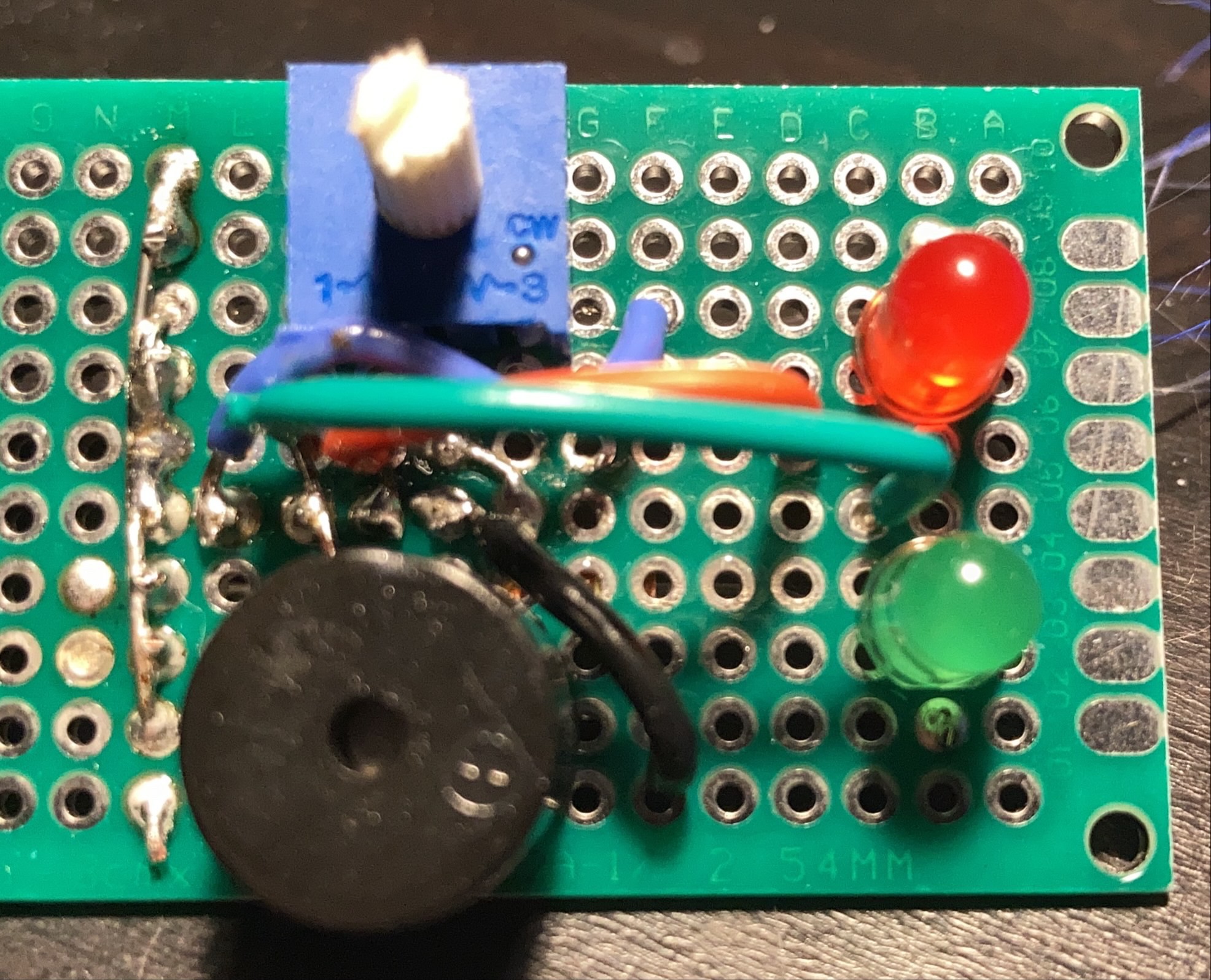
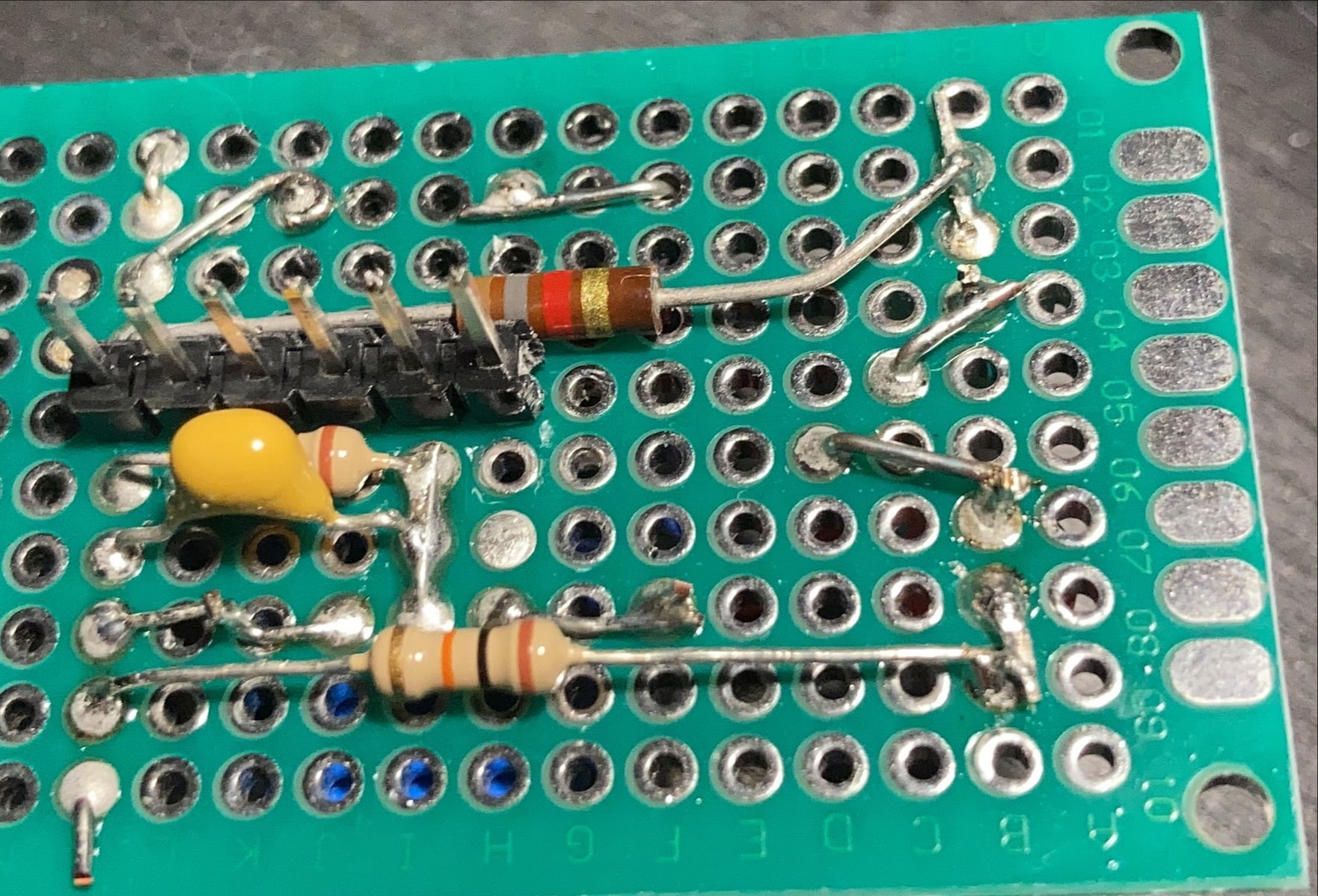
Out of Time
All of this got done on the Saturday of Remoticon, so I was more than a little tired at this point. Around 12:30AM local time, I finished up the GKPlus side of the board, tested it (noticing the second red LED was dimmer than I expected), and packed it in. The power switch/power LED/charging LED half will have to wait for another day--preferably before Saturday when I'm risking properly-masked-and-social-distanced contact with my friend in his garage to drill holes and cut windows for mounting everything.
The firmware will get finished after that; it turns out I'm down to looking for 100-byte scale savings and I still have more features to implement. Eventually. :)
 Jon Kunkee
Discussions
Become a Hackaday.io Member
Create an account to leave a comment. Already have an account? Log In.