 land-boards.com
Since the 3-Chip Z80 allows the PSoC to load the SRAM and control the Z80 it would be fun to imagine how a front panel would work. Something like one of those very classic front panels with switches and LEDs on it. But re-imagined for the present.
What I don't care for about the original front panels is the expensive rocker switches. They look retro-cool, but cost a lot of money. For this design, I'm going with clicky pushbutton switches and using software on the PSoC along with the LEDs on the board to treat the switches as if they were toggle switches. Push a button and the corresponding LED toggles on or off.
For this we need 16 address, 8 data and some number of control switches/LEDs.
Hardware
The PSoC has an I2C bus. I've designed an I2C card with 4 of MCP23017 16-bit port expanders. Each of the port expanders has 16 bits of I/O. Here's what I came up with for a PCB design.
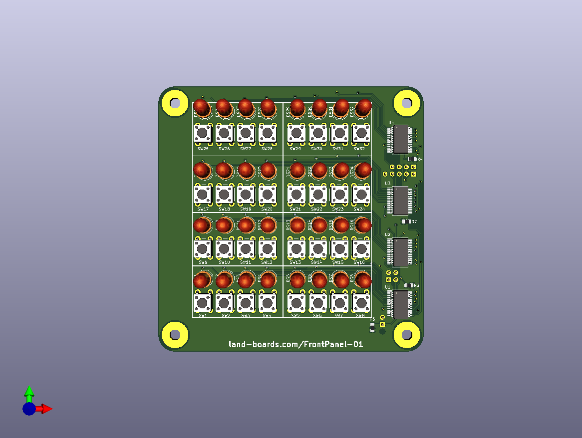
There are four rows of 8 switches and 8 LEDs. Each switch and led is connected to individual lines into the MPC2017 chips. These take up 4 I2C addresses - either 0x20-0x23 or 0x24-0x27. The I2C A2 address value is selectable via jumper.
The I2C bus uses SDA and SCL plus Power/Ground. There's an interrupt from the card for change of input states which is programmable in the MCP23017. There's a daisy-chain connector to allow other I2C devices to be chained off the first device. There are jumper selectable terminators on the card as well. These are all accessible from the rear of the card.
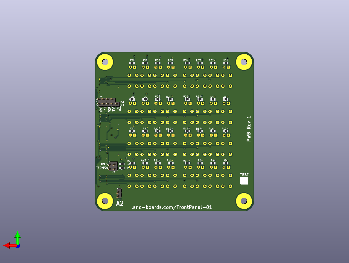
The card could be stacked with the 3-Chip Z80 card and wiring brought from the I2C interface on the top side of the Z80 card up to the back of this card. The two cards have the same ODAS 95x95mm design with 6-32 mounting holes in the same spots for stacking with stand-off hardware.
Software
The Software to talk to the Front Panel is all contained inside the PSoC. The software detects key presses and sets LEDs accordingly.
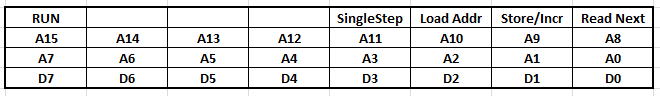
A notional button/LED setup is something like this:
When an interrupt is received the PSoC goes to the I2C bus and determines which bit was changed. The PSoC is responsible for key debouncing which it can do by reading the buttons several times. Pressing D0 for instance, will toggle the value of the D0 LED.
The top row of buttons tell the PSoC to do operations like:
- Run the program from the address on the address LEDs (A15..A0)
- Single step the program from the address on the address LEDs
- Load Addr lets the address that is currently be selected load from memory
- Store increment stores the value that is currently on the data LEDs to the SRAM
- Read Next advances to the next read address in the SRAM and reads the current value (without storing)
This requires a small change to the PSoC design to add an interrupt line from the I2C header. I also added an optional MCP23017 to the PSoC card to all for PIO chip emulation and provide general I/O.
Discussions
Become a Hackaday.io Member
Create an account to leave a comment. Already have an account? Log In.