 land-boards.com
SPoC Code Side
The PSoC will need to poll the IO_Stat_Reg and wait until it sees IORQ* asserted along with either CPURD* or CPUWR*. It should then read the AdrLowIn status register. Using this information, the PSoC should then perform the IO operation.
The main( ) code is actually not idle. It's essentially polling the USB interface. I think the USB is interrupt driven so the code probably just interacts with the handshake to the interrupt. It is currently configured to loop back USB data from the receive to the transmit. I can see this on the PC when I connect to the card using PuTTY. Whatever I type gets echoed back. This will need to be intercepted and routed to the Z80 via the SIO interface.
Data, Status and Ports
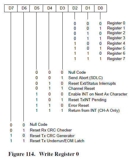
There are four pins provided for an external UART, but I'm going to just toss out the SIO data from the second part for the moment. Using the PSoC debugger to single step, the first write is to the SIO A Control Register with a value of 0. This matches the ASM code.
0403   01A6 3E 00               LD    A,$00
0404   01A8 D3 02               OUT    (SIOA_C),A
0405   01AA 3E 18               LD    A,$18
0406   01AC D3 02               OUT    (SIOA_C),A
SIO Data Sheet
This is when looking at the SIO data sheet comes into play. What does a write to the control register with a value of 0x0 do in the SIO?
The SIO is described in the document Z8420 Peripheral User Manual um0081 starting on p207. There's a lot of information in there about all of the modes that the SIO can do.
Grant's schematic connects the interrupt line from the SIO to the Z80 but that, by itself doesn't mean it is interrupt driven. The Monitor Code has the following:
0139   0062             ;------------------------------------------------------------------------------
0140   0062             ; Serial interrupt handlers
0141   0062             ; Same interrupt called if either of the inputs receives a character
0142   0062             ; so need to check the status of each SIO input.
0143   0062             ;------------------------------------------------------------------------------
0144   0062 F5          serialInt:    PUSH    AF
0145   0063 E5                  PUSH    HL
So, it looks like the hardware and code support interrupts. It looks like there may only be a receive buffer so the interrupts may only be on receive characters. I will have to dig deeper to see if that is the case. It does make sense to have interrupts on receive and wait on output since the buffer could just back up on the transmit side anyway if the host is not ready.
If it's the case that there's only input interrupts then I should be able to get outputs running without worrying about interrupt handling. The console output routine also seems to be polled and waits until the transmit is ready.
0287   0124             ;------------------------------------------------------------------------------
0288   0124             ; Console output routine
0289   0124             ; Use the "primaryIO" flag to determine which output port to send a character.
0290   0124             ;------------------------------------------------------------------------------
0291   0124 F5          conout:        PUSH    AF        ; Store character
0292   0125 3A 8A 40            LD    A,(primaryIO)
0293   0128 FE 00               CP    0
0294   012A 20 0D               JR    NZ,conoutB1
0295   012C 18 01               JR    conoutA1
0296   012E             conoutA:
0297   012E F5                  PUSH    AF
0298   012F
0299   012F CD 42 01    conoutA1:    CALL    CKSIOA        ; See if SIO channel A is finished transmitting
0300   0132 28 FB               JR    Z,conoutA1    ; Loop until SIO flag signals ready
0301   0134 F1                  POP    AF        ; RETrieve character
0302   0135 D3 00               OUT    (SIOA_D),A    ; OUTput the character
0303   0137 C9                  RET

...

0314   0142             ;------------------------------------------------------------------------------
0315   0142             ; I/O status check routine
0316   0142             ; Use the "primaryIO" flag to determine which port to check.
0317   0142             ;------------------------------------------------------------------------------
0318   0142             CKSIOA
0319   0142 97                  SUB    A
0320   0143 D3 02               OUT     (SIOA_C),A
0321   0145 DB 02               IN       A,(SIOA_C)    ; Status byte D2=TX Buff Empty, D0=RX char ready
0322   0147 0F                  RRCA            ; Rotates RX status into Carry Flag,
0323   0148 CB 4F               BIT      1,A        ; Set Zero flag if still transmitting character
0324   014A C9                      RET
The PSoC USB interface ought to be significantly faster than a Serial UART.
Some things, like bits per character, stop bits, parity don't matter for the USB-Serial interface since it's automatically taken care of by the USB transport so writes to those control values can be safely ignored (at least for the USB-Serial port). They will probably need to be taken into account for the 2nd UART interface, but a lot of that is easily handled by the PSoC UART code.
As a side note: M1* will matter when it comes to handling interrupts (from the SIO datasheet)
M1 Machine Cycle One (input from Z80 CPU, active Low). When M1 is
active and RD is also active, the Z80 CPU is fetching an instruction from
memory; when M1 is active while IORQ is active, the Z80 SIO accepts
M1 and IORQ as an interrupt acknowledge if the Z80 SIO is the highest
priority device that has interrupted the Z80 CPU.
Hardware handshake is also not an issue for the USB-Serial port since it's also taken care of by the USB protocol.
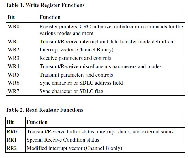
The SIO datasheet shows that there are multiple registers which apparently are selected by a write to the first location.
These registers can be represented in C by variables.
WR0
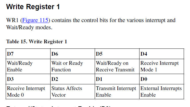
WR1:
Re-writing Grant's SIO initialization code as psuedo-code:
; SIO Initialization code in Grant's monitor
; Set up Port A
SIOA_C = $00        ; WR0
SIOA_C = $18        ; Channel A reset

SIOA_C = $04        ; Select WR4
SIOA_C = $C4        ; X64 clock rate, 1 stop bit, no parity

SIOA_C = $01        ; Select WR1
SIOA_C = $18        ; Rx int on all rx chars, no Tx int enable

SIOA_C = $03        ; Select WR3
SIOA_C = $E1        ; 8 bits/char, auto enable CTS, Rx Enable

SIOA_C = $05        ; Select WR5
SIOA_C = RTS_LOW    ; RTS = LOW

; Set up Port B
SIOB_C = $00        ; Select WR0
SIOB_C = $18        ; Channel A reset

SIOB_C = $04        ; Select WR4
SIOB_C = $C4        ; X64 clock rate, 1 stop bit, no parity

SIOB_C = $01        ; Select WR1
SIOB_C = $18        ; Rx int on all rx chars, no Tx int enable

SIOB_C = $02        ; Select WR2 is Interrupt Vector Register
SIOB_C = $60        ; INTERRUPT VECTOR ADDRESS Value

SIOB_C = $03        ; Select WR3
SIOB_C = $E1        ; 8 bits/char, auto enable CTS, Rx Enable

SIOB_C = $05        ; Select WR5
SIOB_C = RTS_LOW    ; RTS = LOW
I think I could simply ignore any writes to the control registers since I know what they do in Grant's code. This isn't a general purpose emulator, but I don't need to support many of the SCC modes. A more general purpose emulator would need to deal with changes to the registers. All I really need to know is:
- Receive characters are interrupt driven
- Transmit characters are directly written by polling status and then writing
The one thing I do need is the WR2 value since it provides the interrupt vector address. This get supplied back to the Z80 in response to an interrupt acknowledge cycle.
Another possibility is to hard code the fact that these accesses have to come in pairs. The first access is the offset to the register in the second access. I could stuff away the register values based on the second access and hard code this as pairs in the SIO emulator. This seems like the best choice.
Discussions
Become a Hackaday.io Member
Create an account to leave a comment. Already have an account? Log In.