Hey everyone, I have decided to give a more detailed rundown of my project, and some underlying theory.
The goal of this project is to create a PID temperature controller module for use in other projects. This board contains a sensor interface, control processor, and output interface. There are no physical user interfaces on this board, however control via serial, as well as options to interface with displays and buttons for programming will be available.
So, what exactly is a PID controller?
From Wikipedia:
A PID controller is control loop mechanism employing feedback that is widely used in industrial control systems and a variety of other applications requiring continuously modulated control.
It attempts to rectify the difference between the user's desired value (the setpoint) and a measured value (the process variable) by applying a correlation based on Proportional, Integral, and Derivative values (this is where the term, PID comes from). The PID controller can be modeled by the following equation:
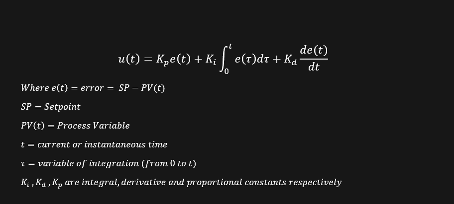
Below is a block diagram to further explain this system.
Here, you can see that the setpoint is summed with the process variable (PV) to calculate error. This value is passed through the PID contoller, where a control variable (CV) is calculated. This value is passed through the plant (the system we are trying to control), and the output from the plant is measured to create the PV. By changing Ki, Kd, and Kp, we can control the behavior of the system. In general, we are changing these parameters to cause the plant's output to equalize at the setpoint, even if a disturbance is applied to the system. The process of adjusting these parameters is called tuning. I will include more about tuning in a later project log.
My PID controller uses a resistor divider network, one resistor being a NTC Thermistor, and an opamp to generate a voltage. This voltage is sent to the ADC on the ATtiny 1614, calculations are performed on the MCU, and then output via the built in DAC. I will include more information about my hardware and how to implement PID loops in software in future updates.
This is meant to be a very basic introduction to both my project, and the concept of PIDs in general. Many different implementations and approaches exist for characterizing PIDs and other control systems, thus this can quickly turn into a long, drawn-out discussion, however, I hope that I was not too long-winded here. If you have any questions or comments, as always, feel free to let me know.
Discussions
Become a Hackaday.io Member
Create an account to leave a comment. Already have an account? Log In.