Project resumes!
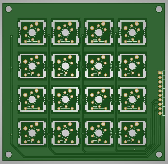
A new set of test PCBs has been ordered - a 4x4 Velocity Switch matrix with breakaway panels.

As the PCB manufacturer (JLCPCB) only does multiples of 5, this one design will be used for 3 purposes.
The Three (identical) PCBs in the stack:
A - breakaway squares are removed and the PCB becomes the plate holding the MX switches (far cheaper than a laser cut plate)
B - MX level - MX switches and diodes soldered
C - Small switch layer - LL1105AF065Q-ND switches and diodes soldered.
The original plan was to use a surface mount switch, but I just found surface mount too small for me to reliably solder. This is why prototype B failed.
So I switched to a THT switch, which helped the design:
- All components are now THT
- The slight increase in height between the B and C levels has allowed for a far simpler method to connected B and C to the control board.
This 4x4 test board will help to test the whole system (design and code) prior to the full size velocity keyboard PCB development.
Just waiting for the PCBs to arrive...
EDIT: JLCPCB have added an additional charge for the routing of the breakaways. In future the Plate will be its own separate PCB
 Redgeneral
Discussions
Become a Hackaday.io Member
Create an account to leave a comment. Already have an account? Log In.