 Matthew James Bellafaire
It’s been awhile since I’ve updated the log for this project. A lot of work has happened on this project since the last update. I’ve assembled the V4 smartwatch and attempted to get it almost working. All the peripheral devices work well battery management and charging are leagues above the previous revision and work great. This project has taught me a lot about design, and although there have been more setbacks then I can count I’m still determined to finish this project and have a smartwatch with everything that I want a smartwatch to be.
With that said it looks like Rev 4 is a partial failure due to the LCD display used for the project. Regardless of what I tried I could not get the smartwatch LCD to work so it’s time to spin another board. If I had a logic analyzer handy, I’d be able to tell with more certainty, but all signs point to the level shifters used to by the display failing to transmit data to the display. I’ve made a few minor edits to the display and decided to go with the same module used in Revisions 1-3, by some miracle I managed to track down the actual LCD module (with no adapter board) on AliExpress (https://www.aliexpress.com/item/32840333697.html?spm=a2g0s.9042311.0.0.529d4c4dVe76Mt) which I’m more than happy to use since it doesn’t cost me an extra couple of millimeters of thickness. I’ve ordered 5 of them since they’re so cheap (and because I was stuck paying $20 shipping anyway) so now I just wait for them to arrive. In the meantime, the electrical schematic has been changed to use this LCD once again following the working parts of the Rev 3 schematic. Using the available libraries for the ST7735 will make the software much easier to write although I do plan to buffer the display for better performance.
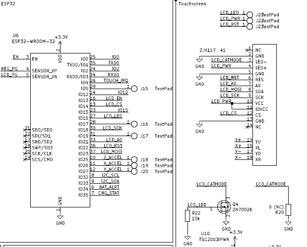
For the most part the next revision (revision 4.1) doesn’t change too much from the previous version, the LCD has been swapped out and there were a few minor edits to connections that I had to bodge in the assembly of rev 4 so lets talk about the newer changes then what works with Rev 4. First things first the LCD:
Changing to the old LCD (ZJY117) opens some pins on the board. I still plan to do a revision 5 where the board gets compacted to fit a wearable formfactor but for now making these edits involved a minimum of layout changes on the PCB side. The LCD itself communicates over SPI with a few extra pins. To save power I have two options for powering the LCD backlight, the primary goal is to have the LCD backlight powered by its own LDO along with the rest of the LCD this way I can ensure that no power is sent to the LCD when not in operation since in previous revisions the LCD drew too much current in standby and resulted in a significant drain to battery life. The LED will be switched by the 2K7002K or by simply applying power to the LDO used by the LCD. I’m not sure yet which of these I’m going to use yet so when I get the newer board, I can select by adding the jumper or the FET.
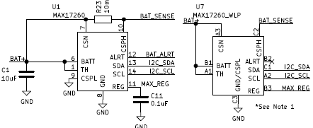
Another problem is that I cannot source the MAX17260 in it’s TDFN package easily from digikey or mouser unless I want to buy 490 of them and wait 3 months. I have a few of the TDFN versions laying around but just to be safe I’ve added the WLP package to be left un-populated if there is no choice and the WLP is the only available IC. This is just to be on the safe side, however using the WLP comes with a price, the ALRT pin cannot be accessed due to the allowed trace size of the PCB so switching to the WLP package does come at something of a price.
For power the design uses two 3.3V regulators which allows me to completely shut down the LCD in software to prevent power drain when not in use. The new LDO takes the place of the previous 2.8V regulator used for the previous LCD.
Since we have extra pins now, I also brought back the accelerometer as an optional addition to the board if everything goes well. In the future this could add additional functionality and another means of waking the device up if desired.
Now onto the positive note of the log, what works.
The new battery management system works much better than the previous version, since everything can be controlled from the software of the ESP32 there’s a lot more flexibility in managing the battery. In previous revisions the battery was automatically disconnected whenever voltage fell below (or went above) a set threshold, this resulted in the device going into complete shutdown without any way to recover. This was an issue because the constant voltage phase of the charging IC would cause the device to shut down until the device had drained enough to re-enable itself.
The newer version also corrected an on-going issue where plugging the device in to charge would interfere with USB communication and result in difficulties uploading code to the watch unless the battery had just the right charge. USB communication in rev 4 works flawlessly and did not require any changes on the new board.
The MAX17260 battery monitor is my favorite feature of the Rev 4 board and allows for easy battery monitoring. To test the performance I created some test code which allows the ESP32 to transmit the battery monitor data directly to a webpage (although most of the credit goes here https://circuits4you.com/2018/11/20/web-server-on-esp32-how-to-update-and-display-sensor-values/ I just modified the code to my purposes). Using this I was able to watch the raw data of the battery monitor as the battery discharged without any connection to my PC. The output webpage looks like this:
Configuring the MAX17260 to work properly wasn’t exactly an easy process but maxim had some useful documentation and startup code to get things started although it wound up being more of an ordeal than expected. Now the code works so I can slot it into the newer smartwatch without too much fuss.
The project is on the right track now and I look forward to testing the Rev 4.1 board. This smartwatch project has been much more difficult than I originally thought when I set out to create my own smartwatch but I’m learning more and more along the way and that’s really the goal of everything I try to do here on my Hackaday.io page.
Hope to see you in the next log!
Discussions
Become a Hackaday.io Member
Create an account to leave a comment. Already have an account? Log In.