 Patrick
The Z stage is not yet finalized, but it's time to look at the XY stage, because we may need to backtrack to the Z once we do a pass on the XY.
First we will look at the belt path. Here were using Gates PowerGrip GT 2 2mm pitch belts, 6mm tall. That seems to be the going setup. The GT 2 belt profile is considered one
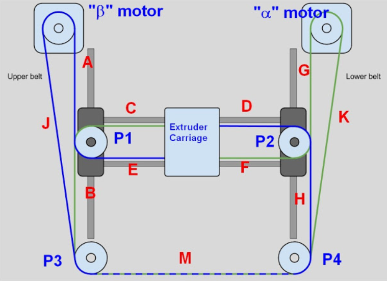
This is from The Digital Dentist on RepRap.org. The key here is you want belts A thru H to be parallel to the X or Y axis. To accomplish that, you need to place the motors and the pulleys at the right locations. So I'm going to start to look at parametrically defining those locations.
Starting from the bottom-up, let's look at the parts we'll be using.
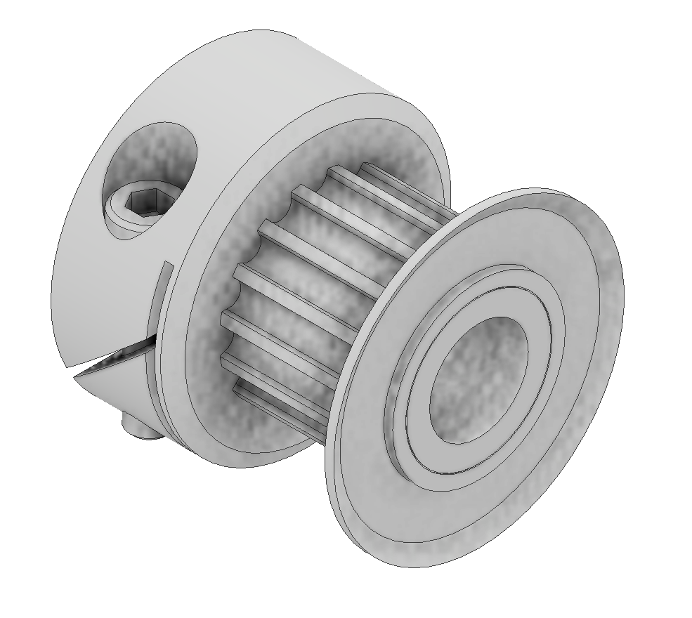
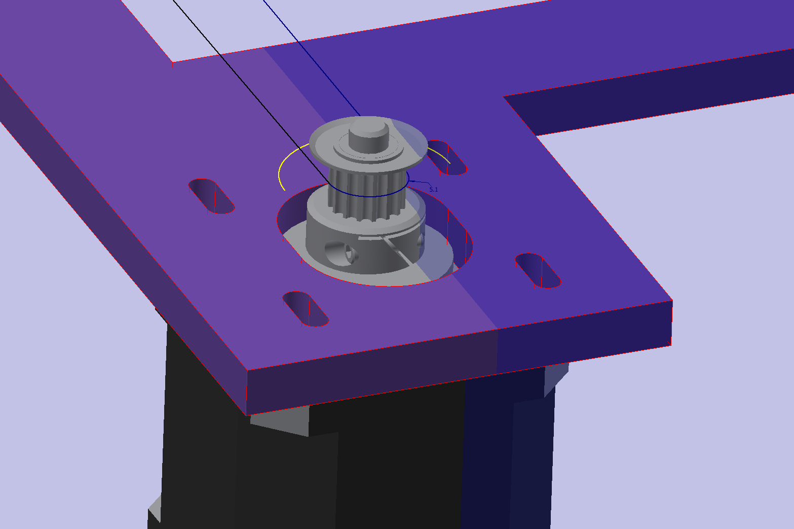
On the stepper motor, I'll be using a 16 tooth GT2 sprocket, this one is a fairloc hub which clamps to the motor shaft. I avoid using a set-screw to attach anything to a shaft. This is a clamping hub, that works really well in a small size. The part is made by Stock Drive Products (SDP-SI) http://shop.sdp-si.com/catalog/product/?id=A_6D51M016DF0605. This part has a pitch diameter of 10.2mm.
Pitch Diameter will be important for all the pulleys, as they define the belt path.
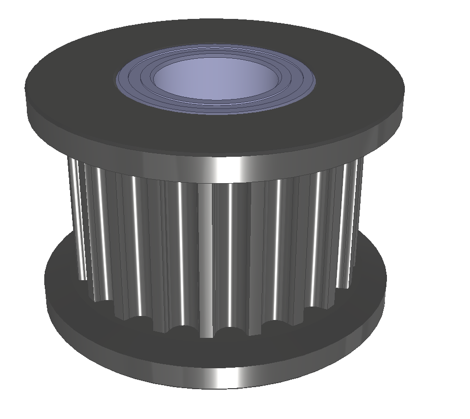
This is a 20 tooth GT2 Idler. It has bearings in the center, fits on a 5mm shaft. https://www.mcmaster.com/3693n11. The Pitch diameter is 12.7mm
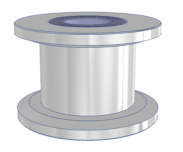
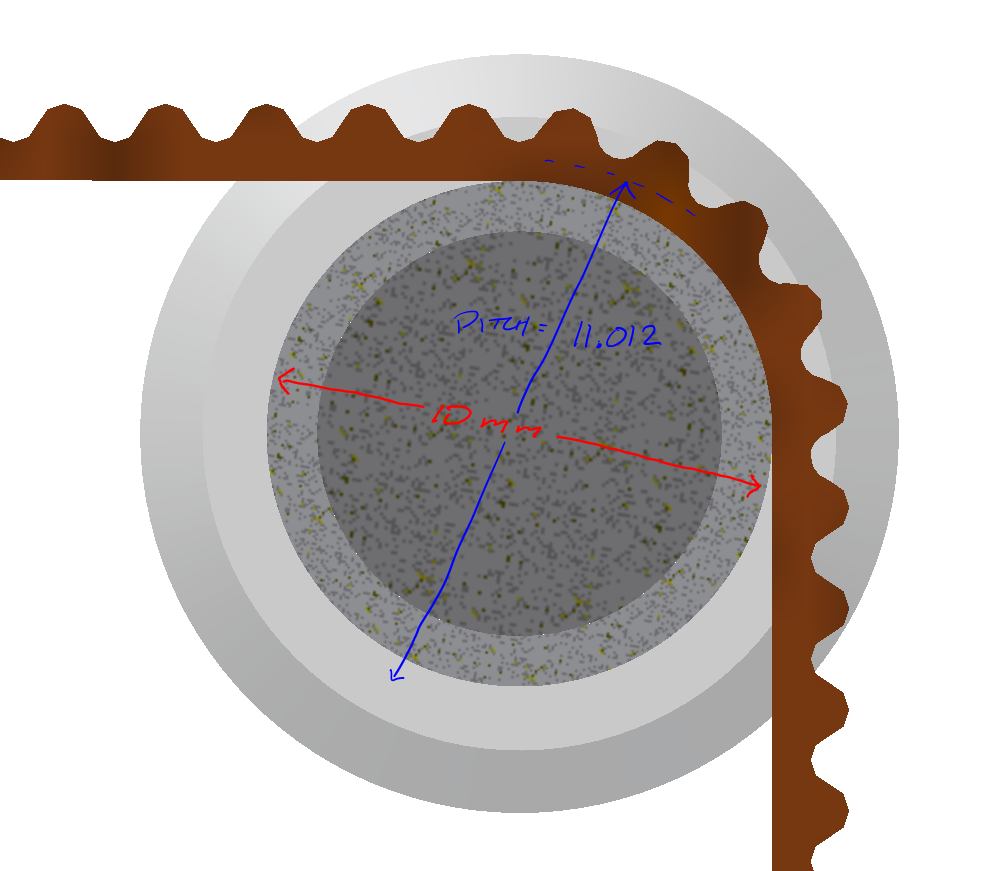
https://www.mcmaster.com/3693n14 This is a belt idler, smooth face, used for running on the back side of the belt. Here the diameter of the pulley is 10mm, which is not the pitch diameter. We need to find that before we go too far.
Both P1 & P2 in the belt path image above are a stacked pulley setup using the 20 tooth idler and the smooth face idler.
P3 & P4 will also be a stacked setup, but I need to determine the larger diameter pulley size. Mandela Rose Works makes a Magnum pulley, but don't publish a mechanical drawing and their parts look a bit rough. I don't like inserting unknowns into my models, so I'll find another way.
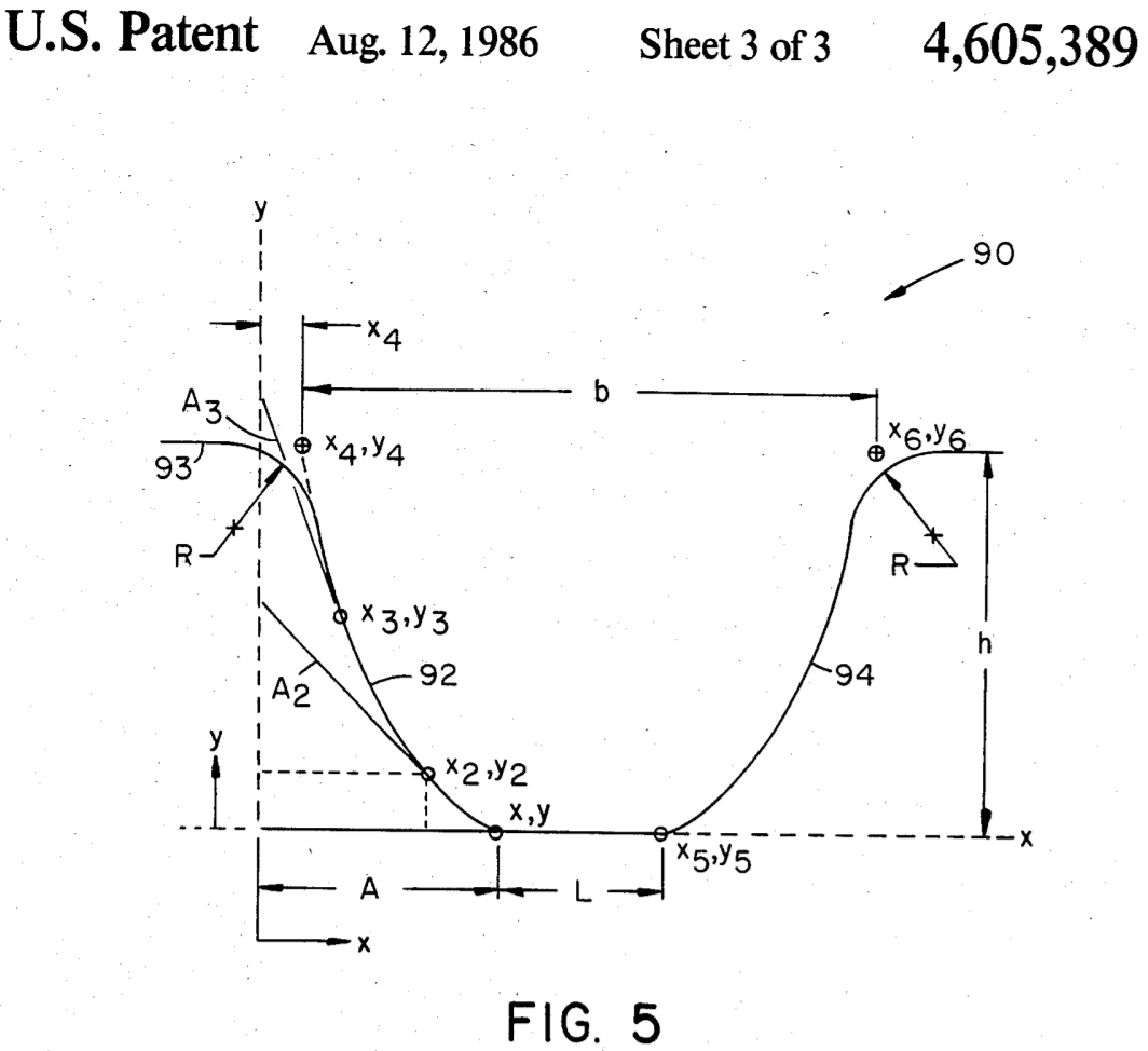
The Gates PowerGrip GT2 belt profile was under patent protection and has since expired. It's a Modified Curvilinear Trapezoidal Timing Belt tooth profile, which makes it a great belt. Detailed info on the belt is difficult to find, there is not much from Gates, except in their patent documents. And it doesn't tell us about the GT2 2mm belt, just the shape of the teeth. Ugh.
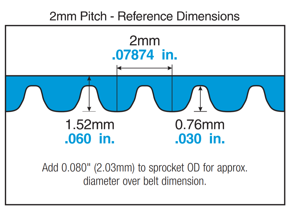 This is from Gate's drivedesign_lightpower.pdf
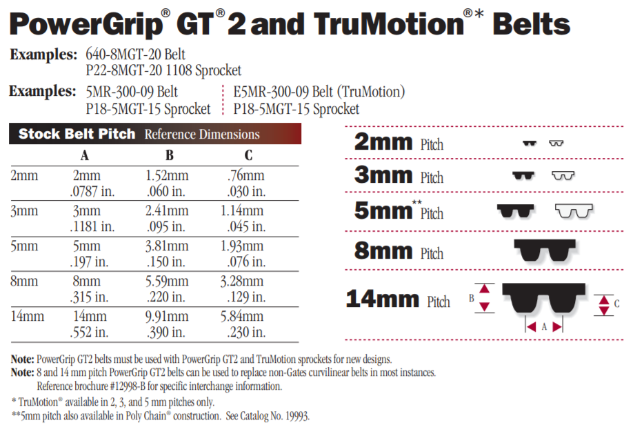
More digging confirms, 1.52mm as the overall belt width, and .76mm as the tooth height.
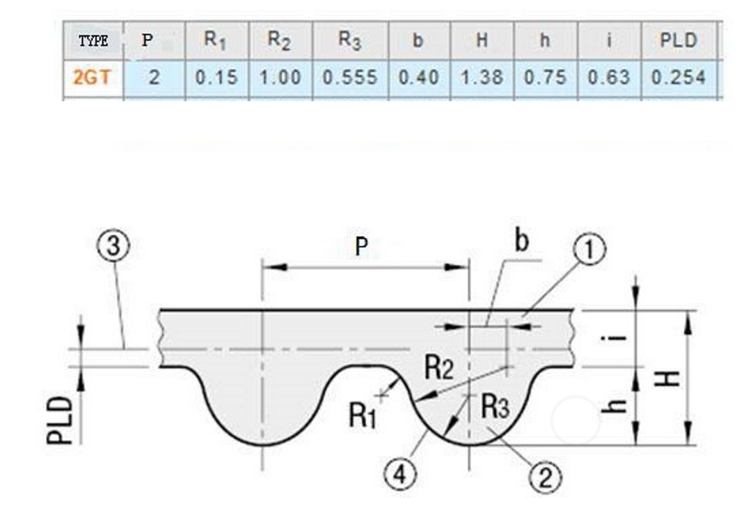
This is from a Gate competitor, someone on Aliexpress I believe. It has more data, but conflicting info compared to the Gates documents.
Specifically, the overall H is 1.38mm here, Gates says its 1.52mm and measuring a worn, but genuine Gates belt, I get 1.48mm. This confirms that I should only use genuine Gates belts.
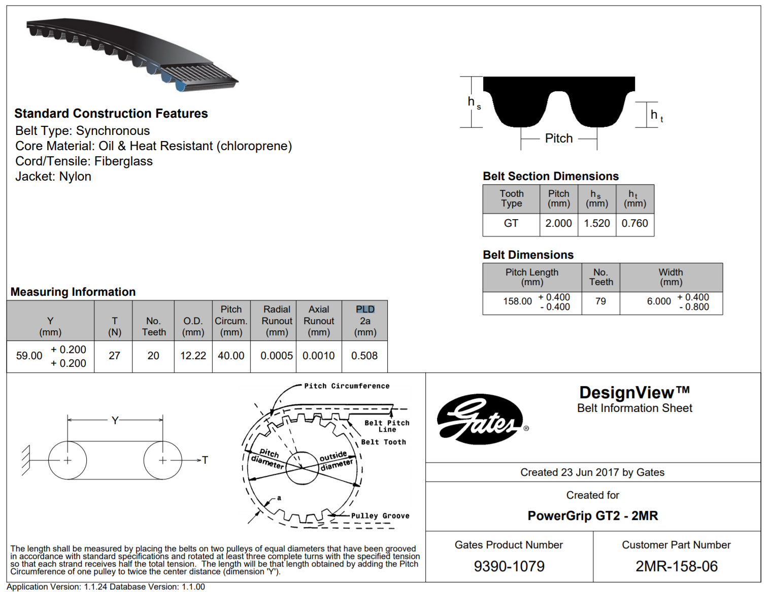
With a bunch of searching, found this document. PLD is .508mm, which I believe is really half that number, .254mm.
Looking at this belt profile, we notice 2 things.
- The dashed line thru the center of the belt is the belt pitch line
- The back face of the belt is offset from the pitch line is:
When it comes to modeling the belt, we will basically just need to define the path of the belt pitch line as it wraps around the pulleys and idlers.
By building the model using the belt pitch line, we can ensure that the belts will be parallel to the axis.
For reference, the PLD is the pitch line differential.
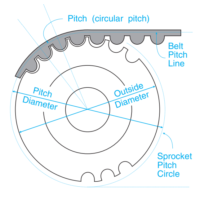
When the belt wraps around a pulley, you simply use the pulley's pitch radius/diameter to determine the path.
On the smooth bore, with the belt teeth away from the idler, the pitch diameter is 11.012 mm. Simply, the pitch radius is = 5mm + (.76-.254), and multiply that by 2.
I'm not yet done with the pitch diameters on the back pulleys, but moving on for now to get something designed.
I roughed up a halo plate, much like the existing one out there. My goal is to be able to fully enclose the MechaCore, so the halo will have to also provide a clean way of boxing in the top. But for now, all I care about is getting the motor and pulley locations defined, with a belt path that is perfectly aligned.
Discussions
Become a Hackaday.io Member
Create an account to leave a comment. Already have an account? Log In.