 George Gardner
At this point I have a panel that is free-running, with the exception of one ISR that executes after every row of data is shifted out. But it can only turn the LEDs on or off. There is no shading. This is where things get fun.
At this point, we'd like to use PWM. Simply set the output enable (OE) pin with a PWM value for each pixel when it is being displayed. However, this will not work. Remember from my first project log that each panel displays 2 rows at a time. So if one pixel should have a shading value of 128 out of 256, or 50%, then all the other pixels in both rows will have that shading value as well. Furthermore, since we're using 4 rows of panels and they all share a common OE pin, it would mean that 8 lines on the entire display (128*8=1024pixels) would all have that 50% shading.
Enter BCM. You can get a primer on it here if you are unaware of what it is. But this will not work in its entirety. The whole idea behind BCM is that you would display your LSB for X clock cycles, then display the 2nd LSB for 2*X clock cycles, next for 4*X, next for 8*x, etc,... And X in this case would be the total time it takes to display 1 row, since you can't display a row faster than it takes to write data to it.
Given the above, it would mean that for the 8th bit of shading we would need (128+64+32+16+8+4+2+1) * (1 row display time), which is unacceptable and would crush any chance of having a decent framerate.
To overcome this, we will use a mixture of both PWM and BCM. Here's how it works:
To get an 8-bit depth of shading, we will implement a PWM on the output enable pin of every panel. When we display the first frame, this PWM value will be 1 and will represent the LSB of the byte (8-bits) we want to display. On the next frame the PWM value will be 2, and will represent the 2nd LSB, and so on. On the 8th frame, the PWM will be a value of 128, and will represent the MSB of the byte we want to display.
A side note on the method above: We have to make sure the PWM is completely off before toggling the latch pins in the ISR, else you'll get TONS of ghosting. On the STM32 devices, running in PWM mode, simply setting the capture compare value to zero will not immediately turn off the PWM. This is because the capture compare value is double buffered, and the capture compare register will not update the shadow register until an update event is generated, which under normal timing settings will not happen until an overflow occurs. Therefore we need to not only set the capture compare value to zero, but we also need to force an update event immediately after to prevent the PWM from finishing out its cycle as shown in the code below.
TIM2->CCR1 = 0;		//turn off display
TIM2->EGR |= (1<<0);	//generate update event to force the above into the shadow register and make sure the pwm stops immediately
So we now have Timer 1 controlling the clock and sending requests to the DMA to transfer all our data, and we have Timer 2 controlling the PWM for the OE.
The above method allows us to create 8 bit (or whatever you choose) shading, using PWM and BCM, all in 8 frames of the display. Moving forward, when I calculate framerate, I'll divide the actual framerate by the bit depth (8), since 8 frames represent a full frame.
Most people say to run 100FPS minimum for LEDs, so your microchip should actually be refreshing the screen 100*8=800 times per second to achieve a fluid look.
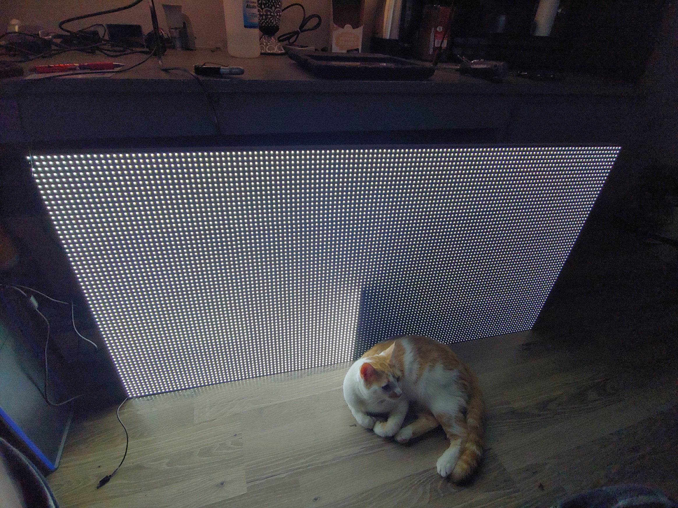
As a side note on this, to my eyes, an FPS of 80 is adequate and sufficient until you try to take a photo of it to share with the community. For this, a framerate of 150+ FPS is desirable. At the time of writing this, my panel is running at 300FPS with 12-bit shading, meaning it's actually refreshing 300*12 = 3,600 times per second. <--And I still have more horsepower under the hood! Bless you, STM.
Discussions
Become a Hackaday.io Member
Create an account to leave a comment. Already have an account? Log In.