 PixJuan
I was thinking that buttons and switches would be straightforward, but I had a few problems. I don't want to recompile my firmware each time I need to change a setting, I could change the settings with commands sent through the serial port, but I would need a terminal running on the PC and won't be able to run games in full screen, so I added switches for :
- resolution (how much I need to turn the crank to simulate a key press)
- key press length
- keymap( which events are assigned to the buttons and the crank)
I did a basic mode, where each switch was used to choose between 2 values for the settings, but that was not enough and also, it was not over-enginneered ;-)
So instead I chose to use the 3 arcade buttons as a 3 bit value between 0 and 5. As I use buttons with leds, the led state is used to display the bit state.
How this value is interpreted depends on the switches positions.
When all the switches are off, the device is in normal playing state and the buttons send keyboard events. If any of the switch is on, the device is in settings mode and the buttons alter the settings
Exemples:
Switches : [X]Resolution [ ]Length [ ]Keymap
Buttons  : [ ]4      [X]2   [ ]1
->setting = 2 for Resolution
Switches : [ ]Resolution [ ]Length [X]Keymap
Buttons  : [X]4      [ ]2   [X]1
->setting 5 (4+1) for Keymap
Switches : [ ]Resolution [ ]Length [ ]Keymap
Buttons  : [ ]4      [ ]2   [X]1
-> game mode, 1 button pressed and sending a keyboard event
It's a detail but I had a bad surprise with the switches. I first tried with regular ones which where behaving correctly, but then I tried fancy ones with leds which needed pulldown resistors. There was no way to use the integrated pull up resistors of the Teensy, otherwise I couldn't light the leds.
For the arcade buttons, I was a bit too optimistic concerning the size of the cable lugs and had to make some additional room for them. Also, as I was working on a Sunday and wanted to get things done I did with what I had at hand. I used jumper cables to connect the buttons where I should have used PCB terminal block connectors. It was a bad idea to use jumper cables for anything else than testing, they tend to unplug and it takes time to debug, I ended up gluing them.
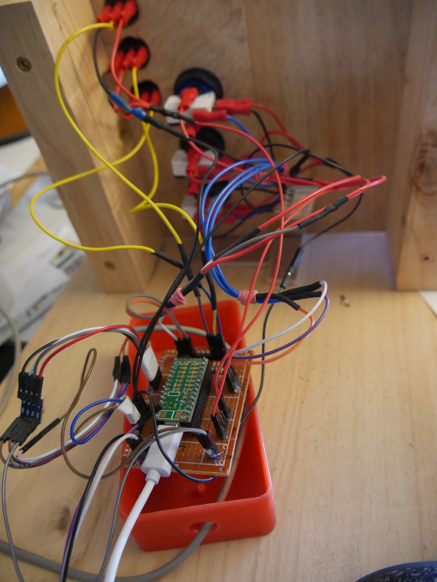
I had to connect a lot of things to the Teensy : 3 buttons, 3 leds, 3 switches and a PS/2 mouse. So I had to make a breakout board.
If you look at the pictures, you'll notice that I soldered row headers upside down on the Teensy I can't remember why but I'm sure I had a good reason at that time ;-)
It didn't matter much since I was not designing my own PCB, just using a prototype board.
I don't know if it is worth designing my own PCB for such a simple task, but I will probably do it anyway to learn how to use Kicad.
Discussions
Become a Hackaday.io Member
Create an account to leave a comment. Already have an account? Log In.