Close
0%
0%

How to make Audio amplifier with 2N7000 MOSFET

The circuit for Audio Amplifier is made on Vero-board which stimulates and amplifies the input sound by using a battery.

Similar projects worth following
The circuit is also checked in Simulink for successful stimulation before utilizing it on breadboard. The components used in the circuit are mentioned in the report with their respective details which are required. The values of resistors and capacitors are calculated according to the calculations taught in the Lab work. The report also contains the details of the pins configuration of the components attached in the circuit for Audio Amplifier.

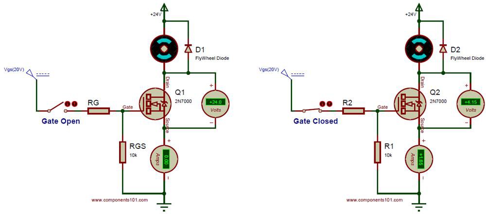
A MOSFET, Metal Oxide Semiconductor Field Effect Transistor is used for amplifying or switching electronic signals. The body of a MOSFET is usually connected to the source terminal which makes it a three-terminal device similar to other FETs. The gate voltage opens or closes a conducting channel between source and drain.  

CIRCUIT DEMONSTRATION

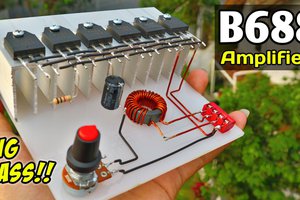
  • The audio amplifier we made using MOSFET according to the circuit diagram given below.
  • We first calculated the values of the resistors and made the voltage dividing circuit on proteus and simulated it.
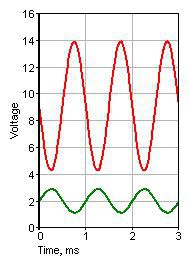
  • The waveform we observed was some bit amplified. So that we moved further instead of making our gain high enough.
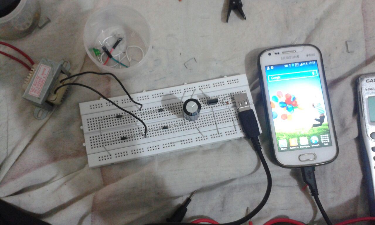
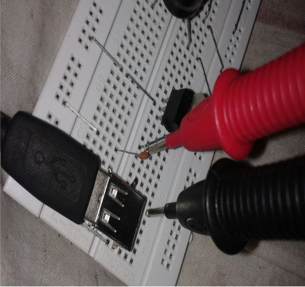
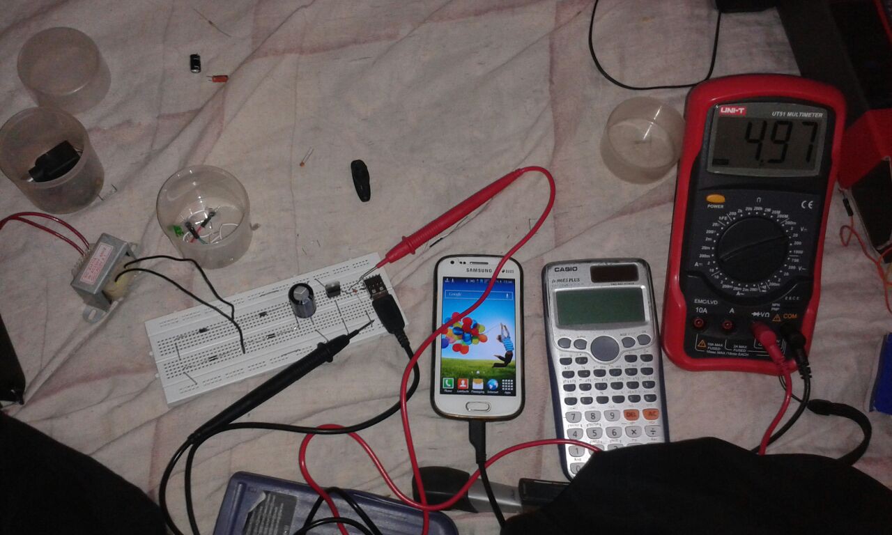
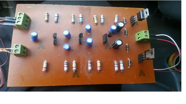
  • We Made hardware circuit according to circuit diagram.
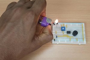
  • First, we have test circuit on bread board and then we have made it on PCB.
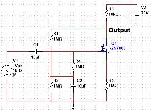
                                                                  (circuit diagram)

WAVEFORM

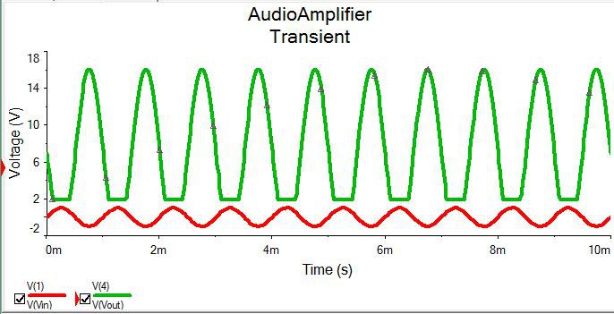
                                                     Output of Multisim Software,

                                                           Green = Output

                                                            Red = Input


  • 1 × 2n7000 NMOSFET https://www.utsource.net/sch/2N7000
  • 1 × Resistor. (10kΩ, 6.8kΩ, 2.5kΩ, 1.5kΩ)
  • 1 × Capacitor. (100µF,1000µF)
  • 1 × Speaker. (8Ω and 1W)
  • 1 × Jack. (3.5mm)

View all 6 components

  • 1
    Hardware testing on bread Board

    Hardware testing on bread Board

    Input Jack of Amplifier 

    Input Voltage of Amplifier 

    Finalized Circuit on PCB

View all instructions

Enjoy this project?

Share

Discussions

Similar Projects

Does this project spark your interest?

Become a member to follow this project and never miss any updates