 Michael Gardi
When I was thinking about and doing research for this project I happened upon the following article Building a 4-Bit Computer: Relay Based Hardware Accelerators by Max Maxfield. This and it's associated articles were very interesting and informative. At one point Max and his collaborator Joe Farr talk about implementing the computer: "...the idea is that we will have a series of glass-fronted wooden cabinets mounted on the wall. One will contain the Clock Generator, another will contain the CPU, and yet another will contain a Programmer’s Console...", much like the Working Digital Computer's design I thought. The part that really caught my interest was:
"The fun thing is that the contents of each cabinet will be realized using different implementation technologies, including relays, vacuum tubes, transistors, jelly bean 74-series logic chips, magnetic logic, pneumatic logic, fluidic logic… we are limited only by our imaginations."
That did sound like fun so I decided that this is what I would do as well.
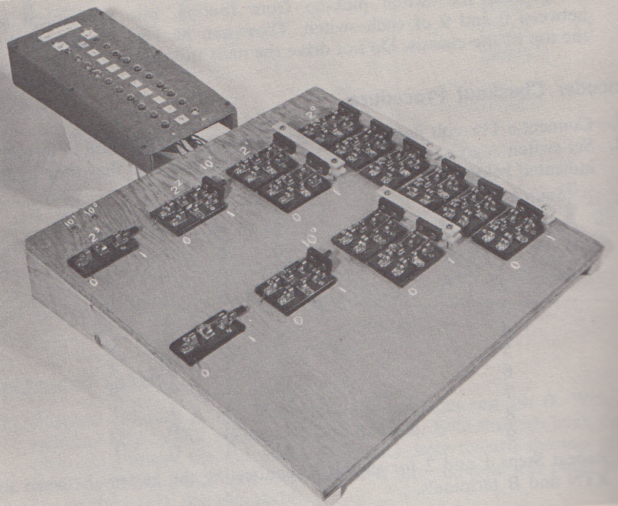
Getting back to the Output Panel. While the Output Display part was relatively compact, the Decoder circuit to power it was enormous consisting of 12 DPDT and 2 SPDT blade switches mounted of a 15 x 15 inch board.
At first I thought that I might implement the Decoder with relays rather than hard wiring it since a bunch of 5V signal relays had just been donated to my makerspace (Kwartzlab Makerspace). I found the following circuit:
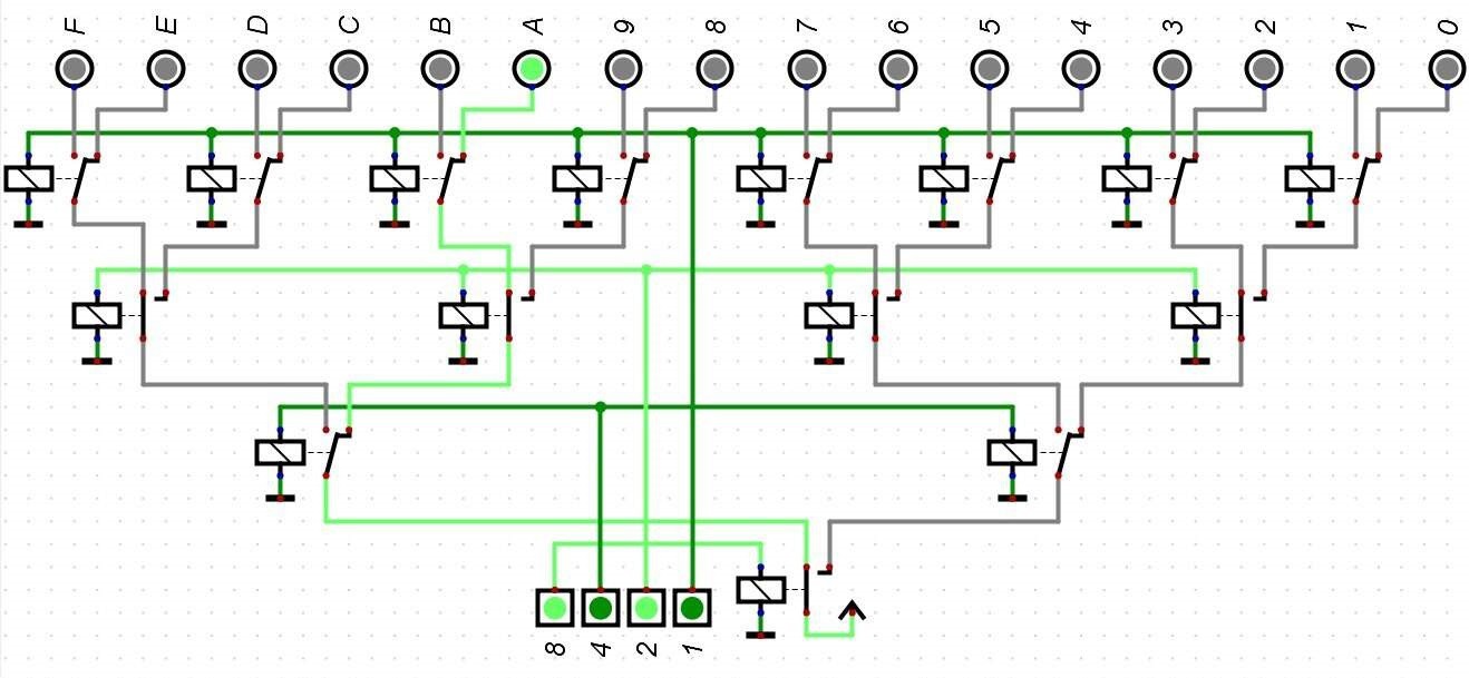
It would cost 7 DPDT and 1 SPST relays per decoder, and I would need at least two decoders. Not bad, but making even two decoders would eat up most of my stash of relays and I was pretty sure that I would need more than two decoders for the rest of the build. So I turned my attention to the 7400 series ICs. Since the 7400 series of TTL logic integrated circuits was introduced in October 1966 I felt they were mostly "on-side" for this project (remember my goal is "period technology" with modern fabrication). I had not actually ever implemented anything substantial with 7400 logic so I was intrigued. The following circuit seemed both simple and elegant:
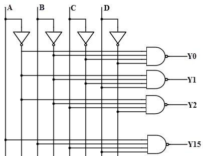
This circuit would require 1 SN7404 (Inverter 6-Channel ) and 5 (since I would only implement for 0-9) SN7421 (Dual 4-Input AND Gate). At a cost of less than a dollar per chip pretty reasonable. Having decided on the technology the next step was implementation. Proto board and point-to-point wiring was certainly an option but at the end of the day I chose to design a PCB. I had not done any PCB layout for quite some time and I had forgotten how much I enjoyed doing this work, getting the parts into just the right orientation for a clean board. Mind you I have never done anything really sophisticated, just simple 2 layer work like this one:

Now the board is wired for the full 16-bits of output, but for the decoders only 10-bits will be used. And the board:

turned out pretty good. Some of the text was in Top Documentation not Top Silkscreen so didn't get printed, plus I have since added the limiting resistor for the LEDs to the board but it will do for my purposes.
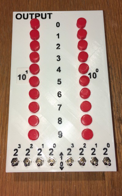
With the 7400 based Decoders, the 15 x 15 inch board from the book has been reduced to a single row of toggle switches and a couple of PCBs. Here is my Output Panel:
Here is the back:
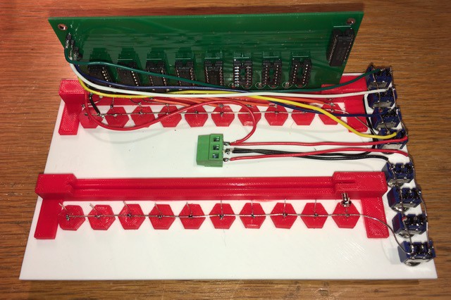
I have designed and printed a couple of brackets to mount the PCBs. One Decoder is wired in and working with the second to follow shortly. Each of the four switches' common lead is connected to the corresponding Decoder input on the board (1, 2, 4, 8). When the switch is set to the down position (0) the input receives a LOW signal. When in the up position the switch signals HI. Works great.
Discussions
Become a Hackaday.io Member
Create an account to leave a comment. Already have an account? Log In.