Overview, Configuration and Operation
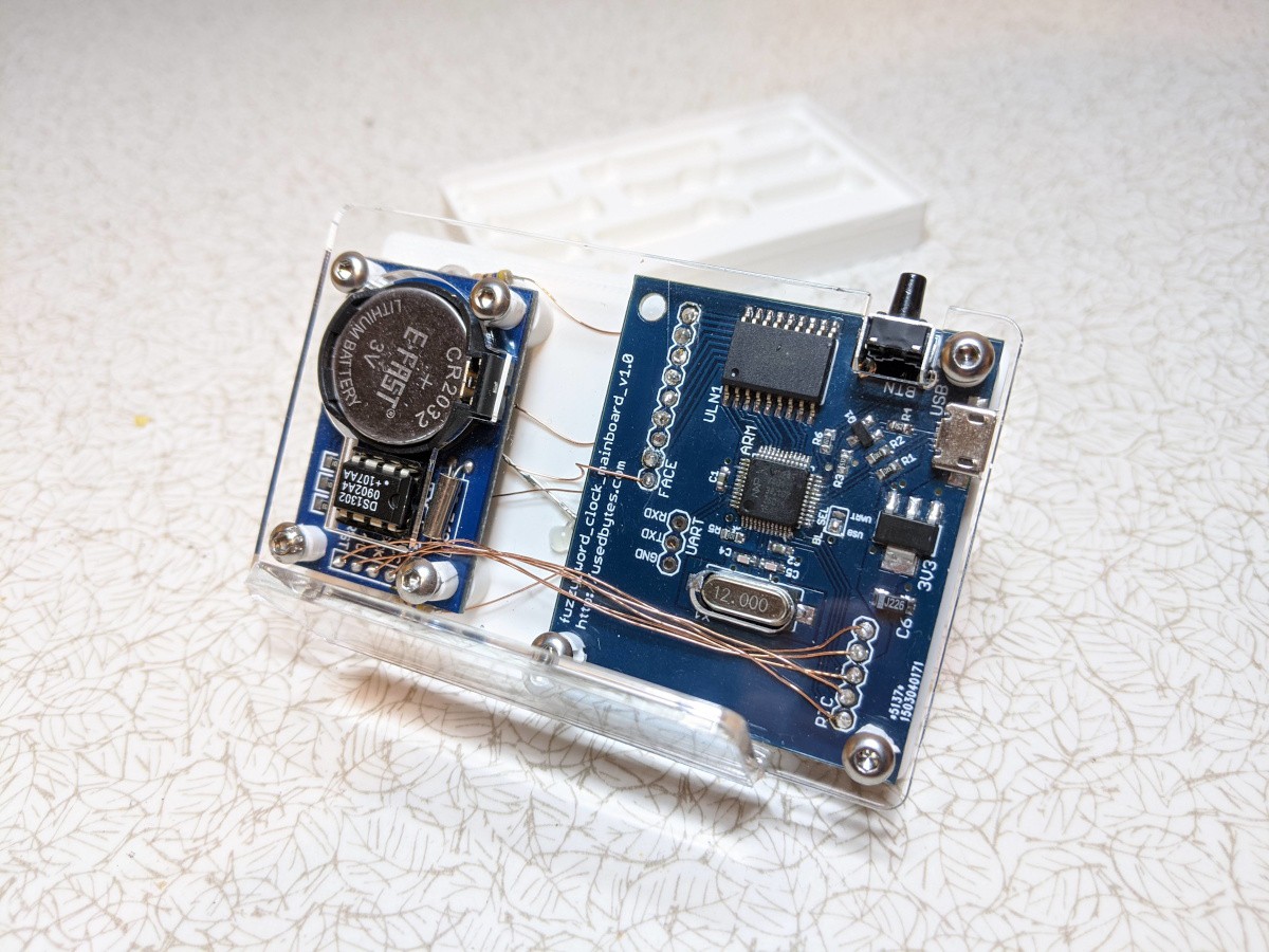
The clock consists of an LPC11U24, DS1302, ULN2803 and white LEDs.
There's a push button which can be used to turn the display off/on. If it's turned off, it will automatically come back on at "nearly breakfast time" the following day. Holding down the button enters "demo mode" where it cycles through all the times.
The clock configuration consists of a number of parameters:
- The time, obviously. Stored into the RTC chip with a battery backup
- A time for each "meal". The defaults match my usual (aspirational) schedule:
- Breakfast - 08:00
- Lunch - 12:20
- Home - 17:30
- Dinner - 19:00
- Bed - 22:00
- A time for "sleep" at which point the display turns off until the next morning
- A time period before each "meal" which counts as "Nearly" (default 15 minutes)
- A time period after each meal which counts as "Past" (default 15 minutes)
- A display brightness
All of the parameters except for the time are stored into the EEPROM on the microcontroller. The RTC chip does have battery-backed SRAM for general purpose storage, but I figured EEPROM made more sense for these mostly static parameters.
All configuration is done over USB serial with a simple set of text commands:
# Set/get the time
SET TIME 2019-12-30-17:03:00
GET TIME

# Set/get a specific "meal" time
SET {BREAKFAST,LUNCH,HOME,DINNER,BED,SLEEP} 01:23
GET {BREAKFAST,LUNCH,HOME,DINNER,BED,SLEEP}

# Set/get the nearly/past times
SET {NEARLY,PAST} 00:15
GET {NEARLY,PAST}

# Set/get display brightness
SET BRIGHTNESS 0xFFFF
GET BRIGHTNESS

# Reboot
RESET
The history of the project is quite long and meandering...
Iteration 1 - January 2014
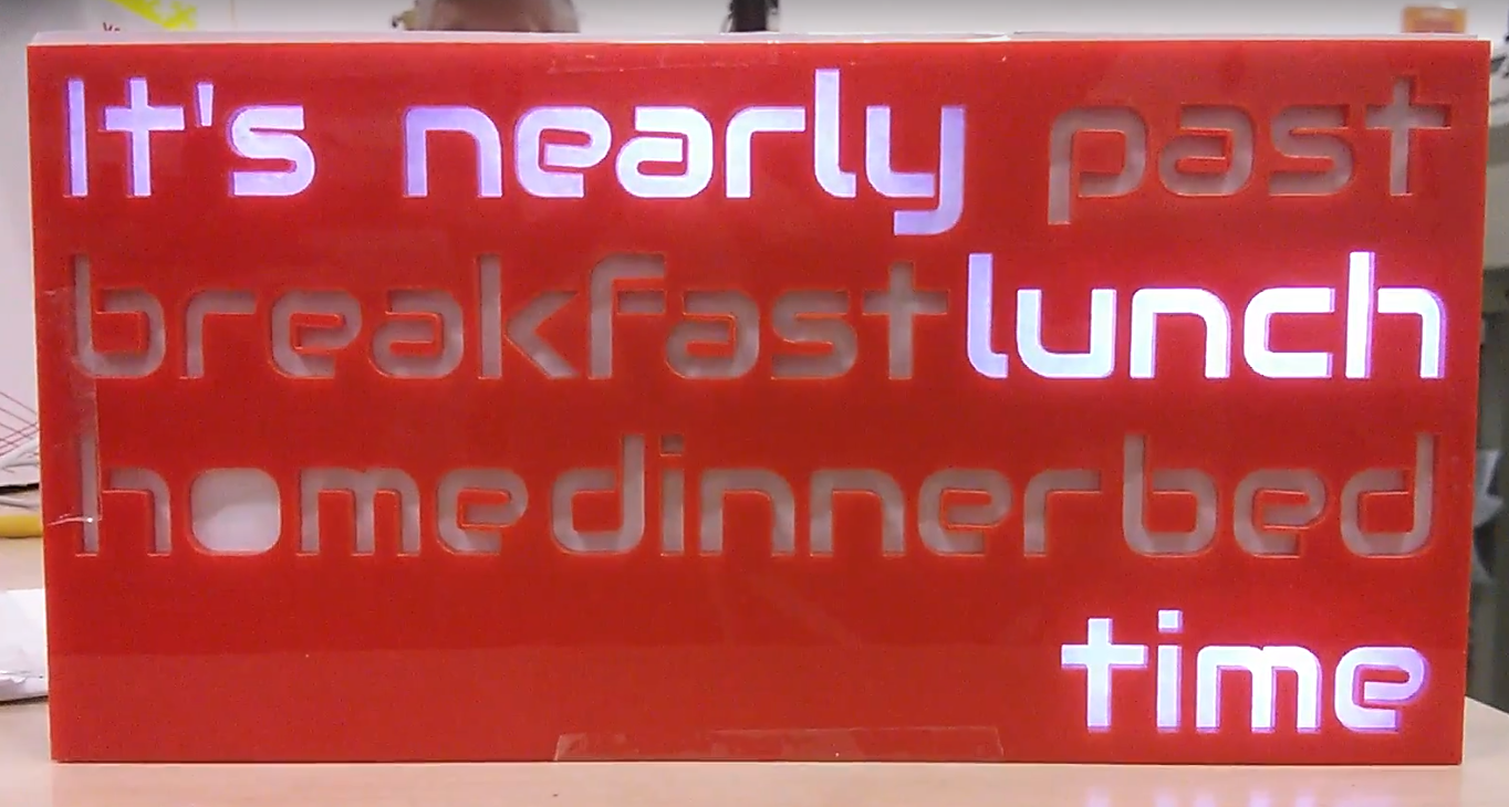
The first attempt was all laser-cut in 3 mm acrylic, with the words cut into the front panel, a set of light-blocking dividers and a piece of white polystyrene as a diffuser.
At the end of 2012, TI had run a giveaway for their new line of Arm MCUs, and I had ordered one, blinked the on-board LED and never touched it since. I figured it had a built-in RTC and lots of I/O so it might make a good choice for the clock. I dusted it off and wrote just enough code to scroll through all the sentences.
At some point before I sorted out actual time-keeping, I got the idea that I'd like to make more than one clock to give to people as gifts, and so the TI Launchpad suddenly looked like a terrible idea as it was hard to get. Also, I never really got on with it, I don't remember the specifics, but the documentation and libraries weren't very good as far as I remember.
Iteration 2 - May 2014
I switched to trying an Attiny2313 instead, because I had a bunch of them in my parts box already.
The Attiny doesn't have any RTC hardware, so I needed a way to get the time. I like the idea of users not having to worry about setting it, so I ordered a 60 kHz radio time receiver module.
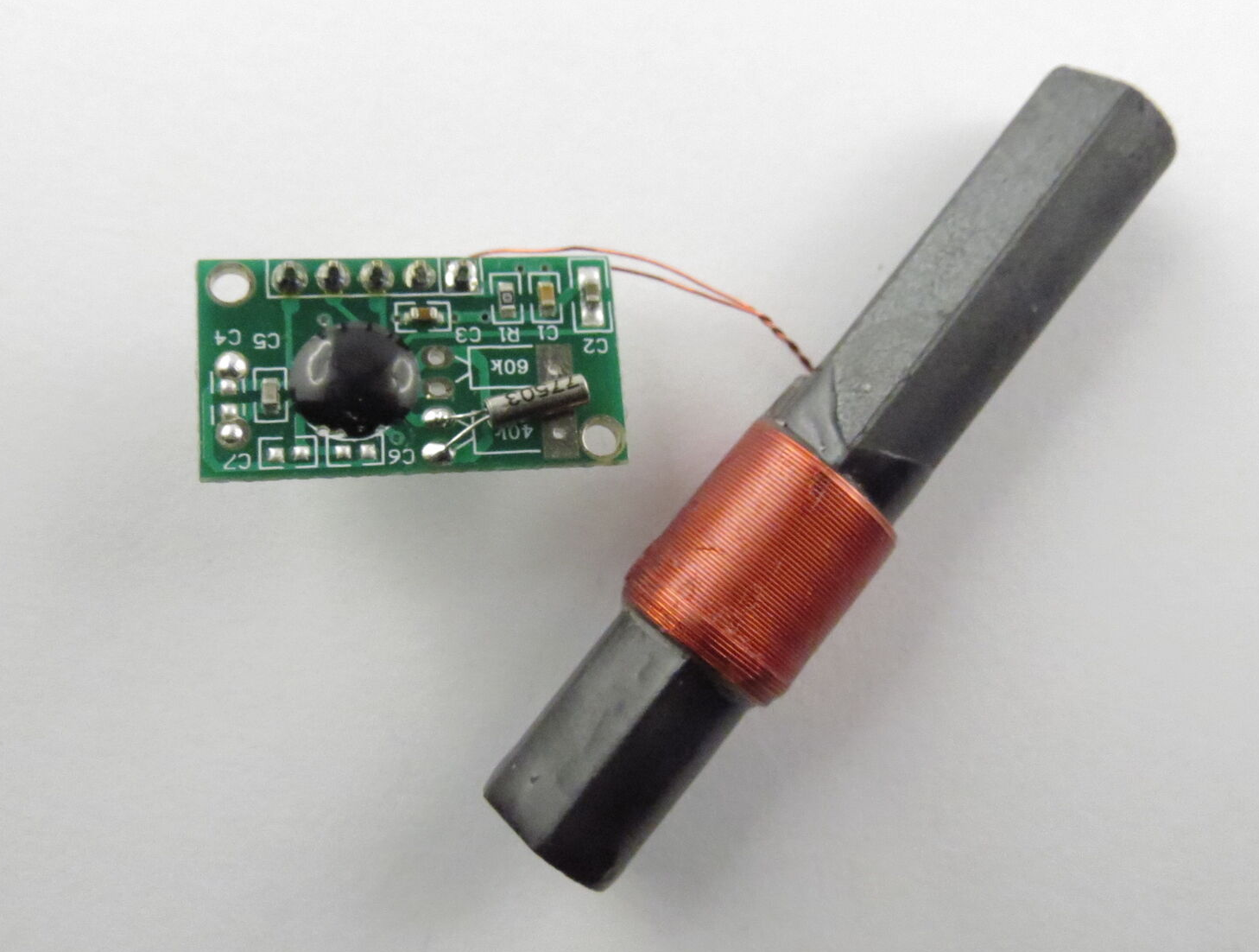
When I hooked up the receiver, it really didn't work well. The signal was too small, and the PWM for the LEDs was introducing a lot of noise. I spent a little time trying to fix that, but analogue electronics was never my strength and I got bored pretty quickly.
Iteration 3 - August 2014
So, I shelved the idea of using the MSF receiver, and ordered a plain boring DS1302 RTC module.
This is a real-time-clock with battery backup, so users would have to set the time, but hopefully only once (...each time the clocks change, because we have daylight savings time here).
That was dead simple to set up, but in the process I ran into the 2kB flash size limit of the Attiny2313.
Around this time, DirtyPCBs hit the news sites. I'd etched a couple of boards myself before with toner transfer, but never done anything with "small" SMD components, so I figured why not design and order a board with an Arm core for the clock?
Iteration 4 - January 2015
I settled on using the NXP LPC11U24 chip for my board. It's Cortex M0-based and has a USB bootloader in ROM which lets you flash code via USB mass storage. It also has USB drivers in ROM for some common device classes - like USB CDC for serial port.
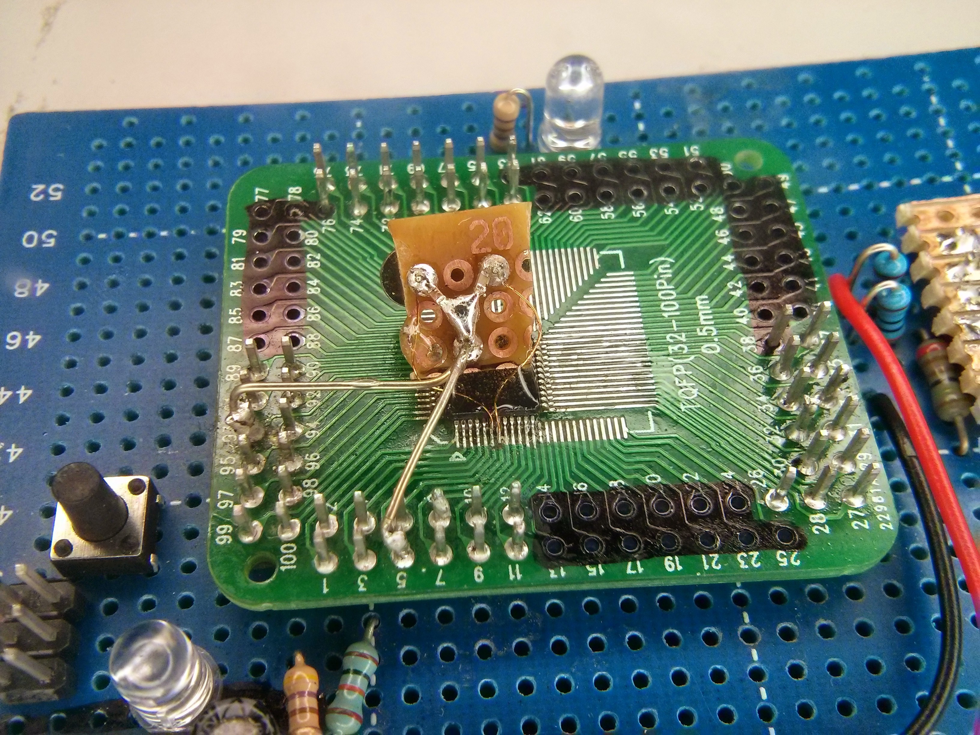
Iteration 4 was really more of a stop-gap prototype. I'd never designed my own Arm board from scratch, so I figured I'd try to test the circuit on protoboard before I sent the board for fabrication. One issue is that the LPC chip is in a TQFP48 package with 0.5mm pitch, which isn't really very compatible with 0.1" protoboard. I got some generic TQFP breakout boards from eBay and built my prototype, also dead-bugging a SMD micro-USB socket.
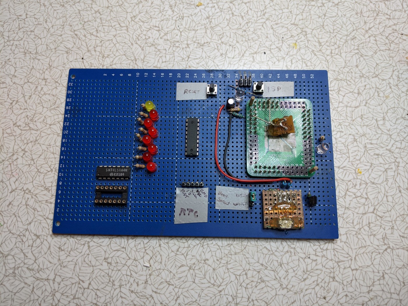
Being used to using the internal RC oscillator on AVRs, I was really paranoid about the high-speed external crystal not working, and so when the chip wasn't working to begin with I assumed it was because of the crystal being far away. I went straight in with a crazy solution to glue the crystal to the top of the chip and connect it with thin wire. It was totally unnecessary - the issue was something entirely different and mundane, like a missing pull-up on RST or something; obviously.
With hindsight, I've mixed feelings about the chip selection. The USB things are convenient, but I ran across several bugs in the ROM drivers. The timers don't have an overflow interrupt (wut?) so you have to burn one of the compare channels to get one. And even though there's four compare channels per timer, it can only do PWM on three of them. I keep running across oddities in the various peripherals which make me go "huh?" (whereas using the STM32F103 feels a lot more logical, to me).
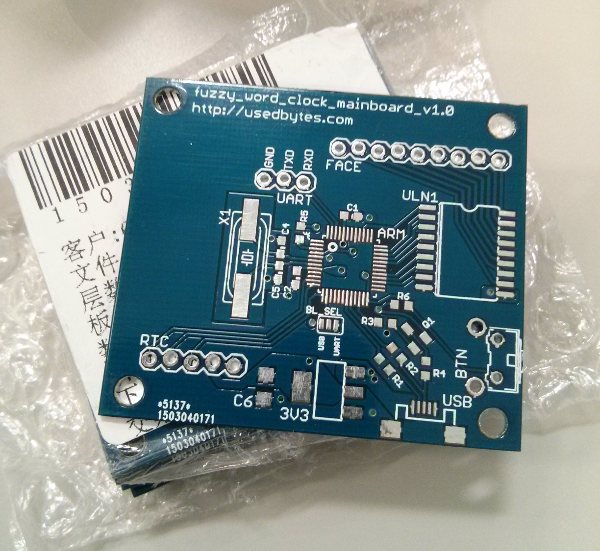
Anyway, I got the prototype working, and got some boards made. I'm pleased to say that there weren't any mistakes (though it does only have around 15 components), however there is a few things I wish I'd done:
- I should have put down a footprint for a reset switch - otherwise development is quite tedious
- I should have put down footprints for the LED resistors. I always intended to have them off-board, but on-board would be so much easier.
- I should have broken out more pins, to make it more useful as a general development board instead of single-purpose.
At this point development stalled. I couldn't come up with a neat and easily reproducible way to bolt everything together. I did some experiments with laser engraving slots for captive nuts, which looked like it could work but it was really fiddly to do.
Iteration 5 - December 2019
Finally (4 years after shelving the project), the Hackaday.io clock contest popped up. I needed a project to work on over the Christmas holidays, so what better excuse to finally bring the fuzzy word clock to some kind of conclusion?
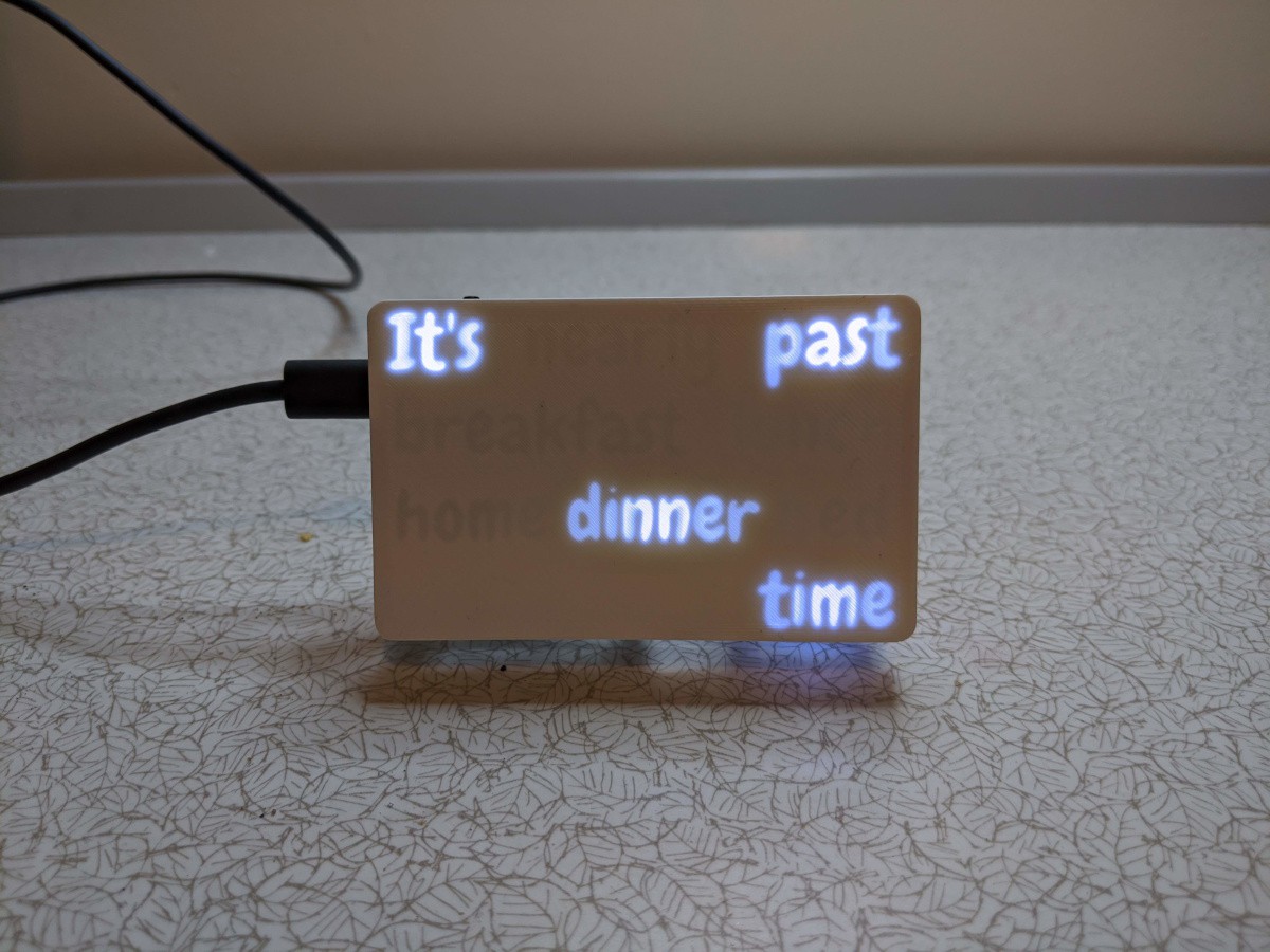
I bought a 3D printer at the start of 2019, and as the lasered acrylic construction was the main sticking point in the design, I figured I'd try printing the clock in a monolithic piece. I'd make the words with a thin front layer letting the light through, with thicker regions forming the letters, visible only when lit up. This design is much smaller - the same dimensions as a credit card and around 25 mm thick.
In the first attempt, I tried to print in a single piece, which meant the part holding the LEDs had to completely bridge significant gaps, and then print circular holes for the LEDs themselves. This didn't work at all, but I knew it was ambitious.
What's a bit more embarrassing is that when it was done, the words were mirrored. On the CAD model, because the words aren't visible from the outside, I hadn't remembered to flip them! A rookie mistake which I think everyone has made at least once :-)
I hurriedly ran off a new version before we drove to my parents' for Christmas. I didn't have time to test it before leaving, and it turns out that the PCB I soldered in 2015 had bad connections on pretty much one whole side of the TQFP package, meaning two LEDs weren't working. I tried fixing the connections with my Dad's huge soldering iron, but without flux or desoldering wick I was scared I'd do more damage than good, and I wouldn't be back home for another two weeks. Instead, I just pushed the pins down hard to bend them onto their pads, and for now it's working OK.
Iteration 6 - January 2020
Iteration 6 is a minor rework to try and improve the light isolation between segments and finalise the wiring and mechanical construction.
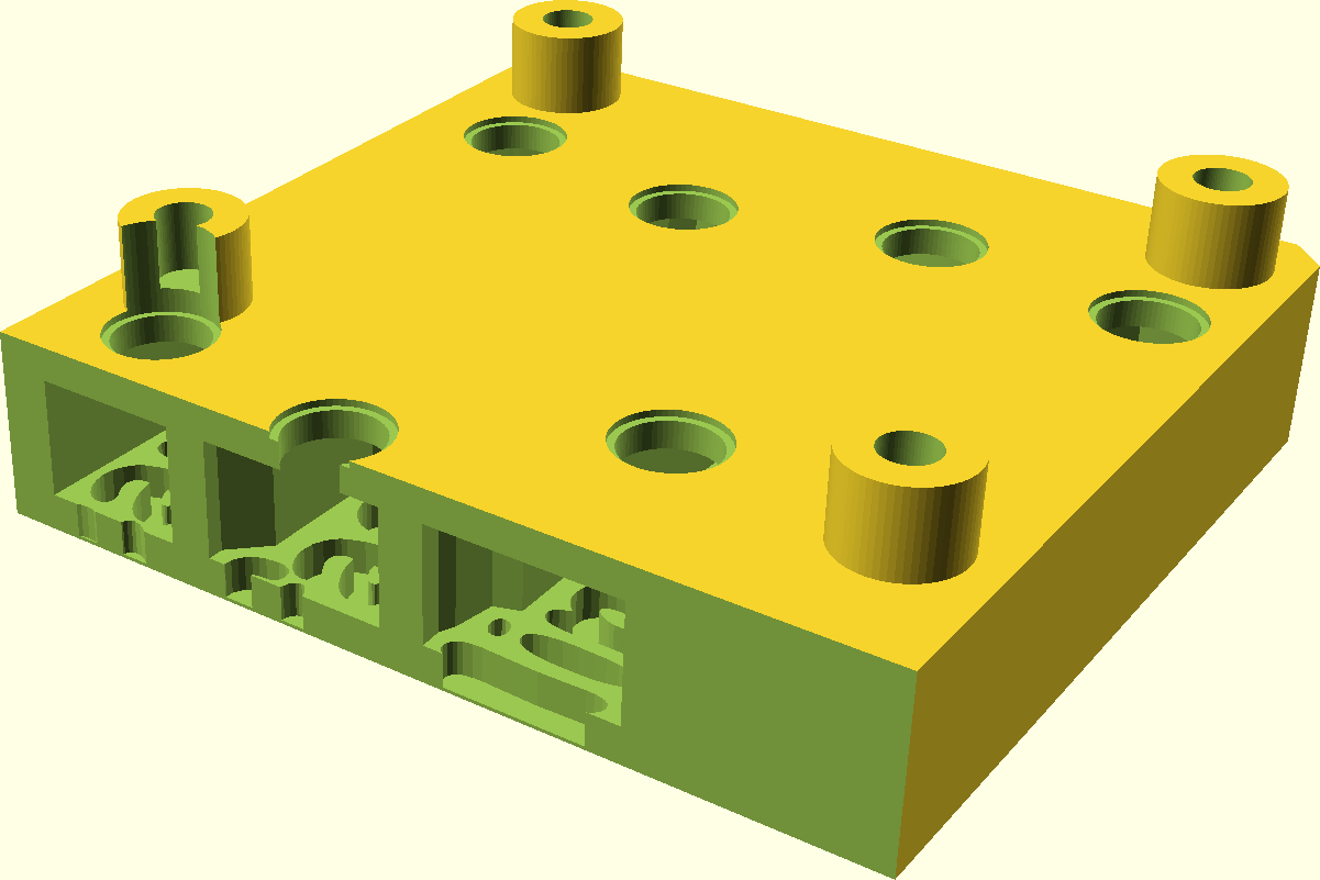
The solid parts on the front face are now 2 mm thick, which reduces the light bleed significantly. I made it so that the piece with the words in has a rim to hold the LED plate in place.
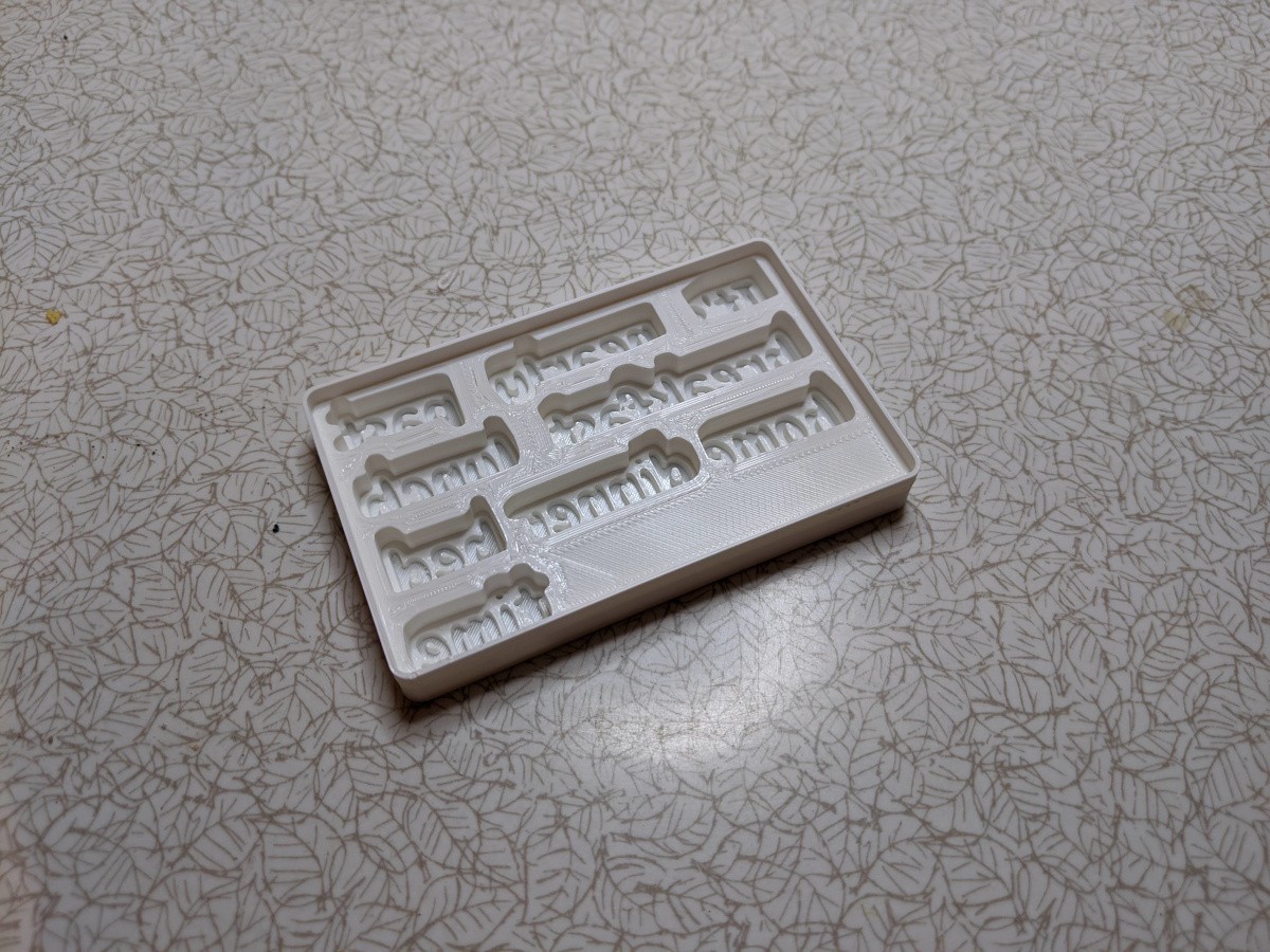
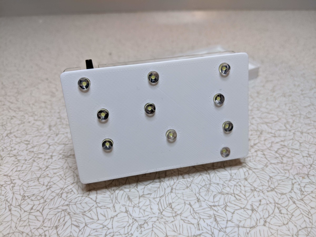
This drops onto the front of the LED plate:
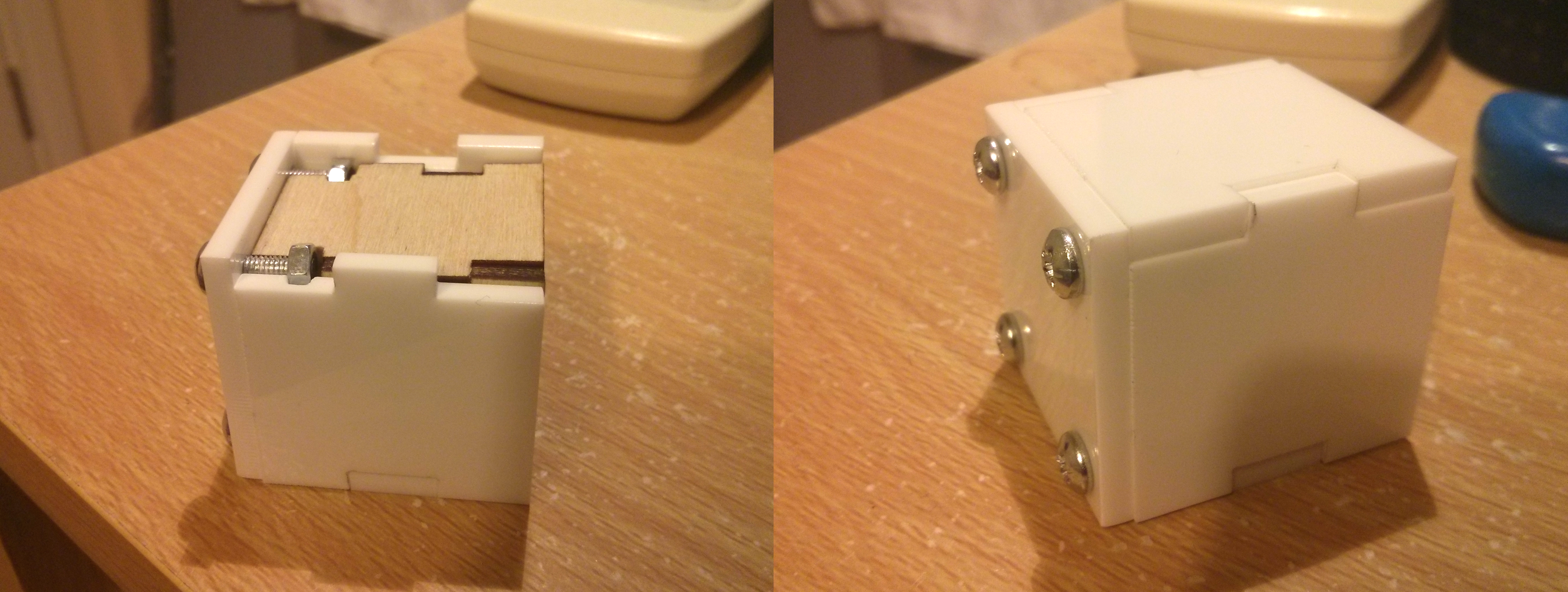
I laser-cut and bent a piece of acrylic to act as a stand and to protect the electronics:
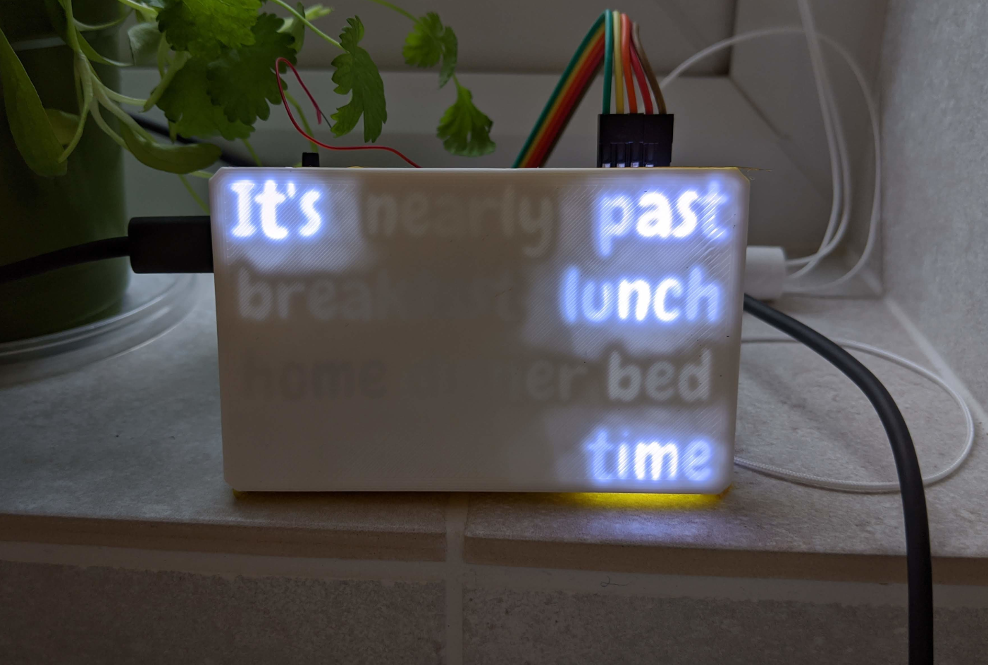
So here's the finished thing: