 Ahron Wayne
By "you" I mean like three really determined fans (you know who you are) and also me!
I've always thought it was very silly for a scanner like this to rely so much on "blind" stitching, or stacking, or 3D model creation. When we have a motorized system and a specified magnification we know at the hardware level to a pretty decent degree of accuracy where we are at all times in the X, Y, and Z dimensions. And yet, we have been stitching by using a vague definition of "approximate overlap" and stacking with external software using no reference data whatsoever and the assumption that images needed to be aligned and resized. This all resulted in images that often looked quite good, but were distorted just enough to make us question whether what we were looking at on the final image mapped correctly to the original source.
And don't get me started on making 3D models by stitching images and then doing photogrammetry on them. It's frankly a miracle that any 3D models were successfully created like this at all --- it's just not what the algorithms were meant for --- and as one professional put it, the 3D aspect of the models was pretty horrible, and it's only the application of color/texture that made them look anywhere decent.
Finally, it's a pain because these are all using different programs. They're not talking to each other and sharing notes. As a result, even though a stacking program can produce a depth map, it's not going to have the same minimum and max height as a different image it makes, and stitching them together will be fruitless.
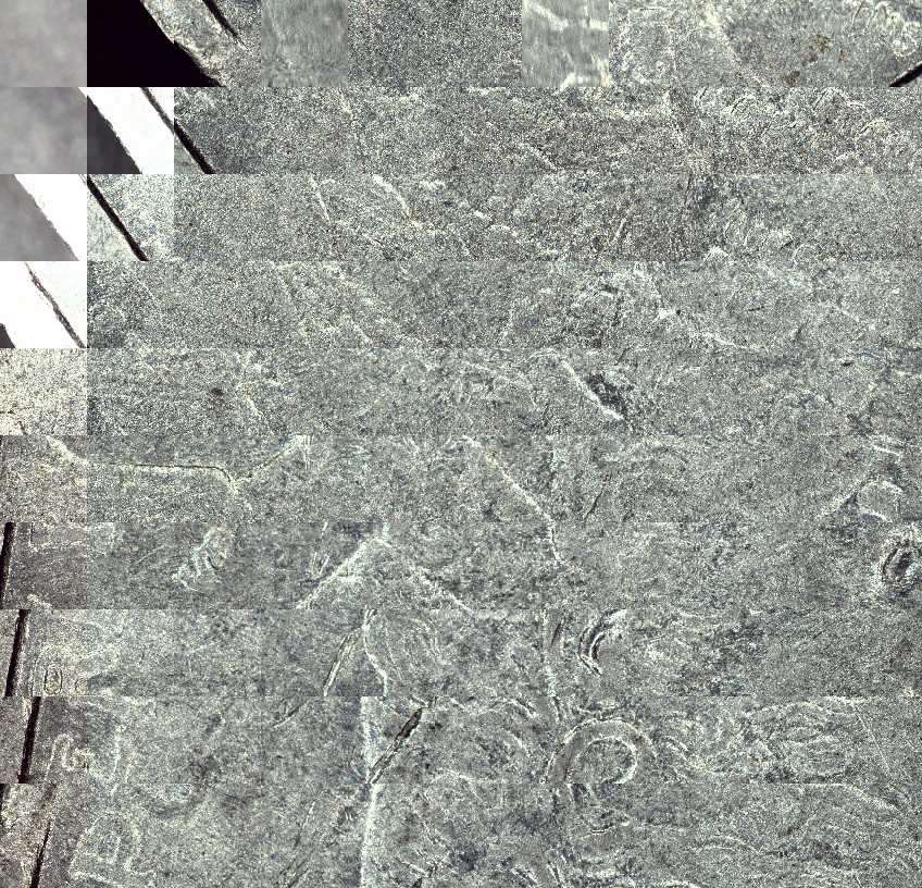
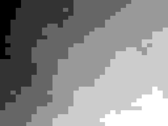
And so I set out to smush input images together using the scanner physical location and known pixel size in mm (approximately). No blending, alignment, or fixing exposure or anything like that at this point. This task intimidated me for a long time because of indexing and matrices, and as expected the first images I created were nonsense like this one:
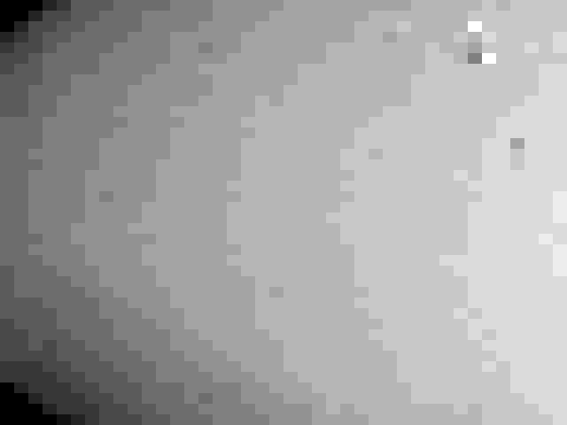
But indexing from the top left instead of the bottom left, and other little fixes like this, ultimately results in the proper image (of a different coin):
The method here is pretty simple: Start with a ridiculously huge giant blank matrix, which I call a "yujieimage" after the person who suggested it, take your position information in XY and convert it to a pixel location using your assumed pixel size, and then index it the proper place on the blank image. This actual smushing operation is basically almost instantaneous. When you're done, just remove all the black areas (surprisingly, the slowest part in the naïve implementation). Also, I'm still not sure what to do about OpenCV's limit on array sizes --- significantly less than the whole build plate would be --- so for testing purposes I'm just doing scans in the corner of my build plate!
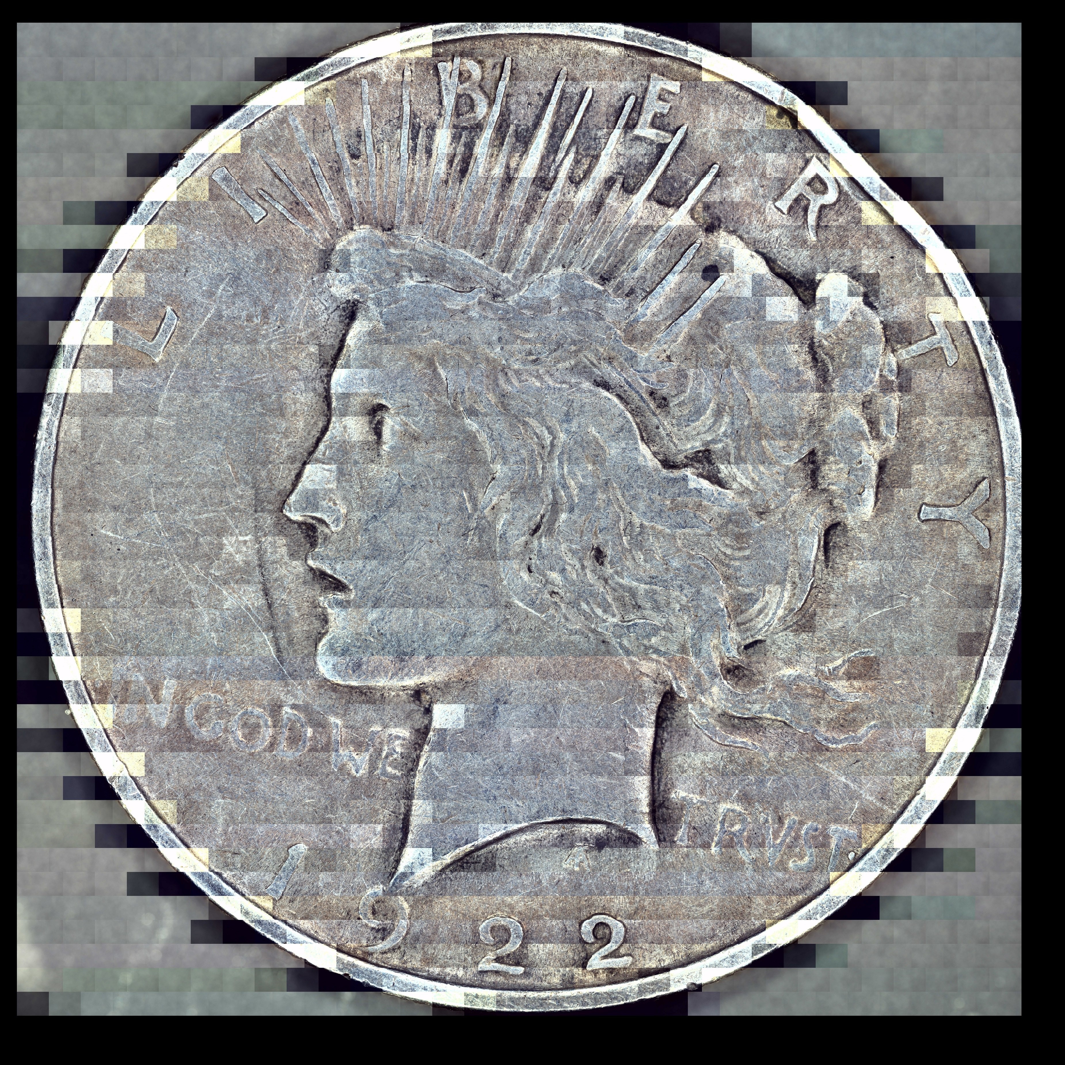
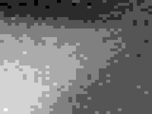
But it works, as you can see with this downscale image for Hackaday's file size limit, and to a surprisingly effective degree. Everything is in the right place almost, and there's no "runaway" error where stitching gets worse and worse over time.
We can also see just how much microsoft ICE has been compensating for our crazy autoexposure. See those alternating bright streaks on the edge of the coin? This is because the autoexposure triggers when hanging off the edge of the coin when the scannner is moving in one direction, and on the body of the coin when moving in the other. Controlling this exposure, dialing in the pixel size a bit more, and doing just a little bit of blending to make stitching lines less noticeable should hopefully be enough to make me abandon dedicated stitching programs altogether forever.
So that's stitching, a huge accomplishment, but we're not even done yet! Moving on to stacking. I can thank Yujie again for implementing the core of the stacking last April. Like any standard focus stacking method, it uses a focus metric to determine which pixels are in focus from a series of images and then assembles the best pixels from all the images into a new image. However, unlike those standard programs, it doesn't align and resize the images --- actually a big advantage for combining with stitching --- and it also breaks the images up into arbitrary chunks instead of doing every pixel. I'll repost this gif to show what that looks like as you make the chunks smaller and smaller:
It's not perfect (especially on speed with small pixel sizes), but it absolutely does work surprisingly well if your object doesn't have sudden Z changes that move around easily, like fur or hair.
With Autocoin in the previous post I was just mixing and matching images before stitching because focus stacking in external software is a pain. But now with stitching programmatically we might as well combine it with stacking and see immediate results around corners and overhangs:
And then last weekend Yujie finally acceded to my request to convert his stacker to also return the index of which image each pixel came from. From there, I was able to map this to the original Z coordinates, and normalize these coordinate to greyscale, resulting in...
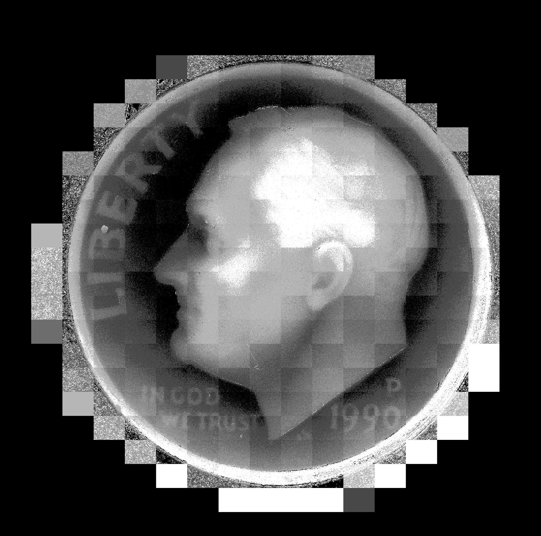
DEPTH MAPS! of various varieties and chunk sizes! Booyah! The next logical step was to stitch them together (before normalization, while the maps still corresponded to true Z heights). And so I did. I popped in a dime, held my breath, ran the scan and this resulted in:
um... well, that's disappointing. I guess you can kind of see his ear, or something? And the general outline of his head, and the edge of the coin? This was really sad. I guess the variation of depth just wasn't nearly as much as I thought of the coin.
And yet... clearly, it was, because depth maps of individual non-stitched images showed more variation than this wide field of view. And the whole point of my neededing to do these Z stacks in the first place was because of depth variation. I tried scanning an even higher-relief coin and got a similar crappy image. There must be some kind of bug...
After hours of searching, the only possible contender was the point where I was stitching the images together. And then it hit me: I had an array of Z heights that I was stitching together, and then normalizing them. Except the Z heights were floats, and the image arrays were integers, and... oh.
Instead of returning an error, it helpfully rounded them for me, and Z heights of 4.1,4.2,4.3,4.4,4.5, and 4.6 would all just become... 4. Okay, so let's just stick with floats until you've converted it to grayscale and...

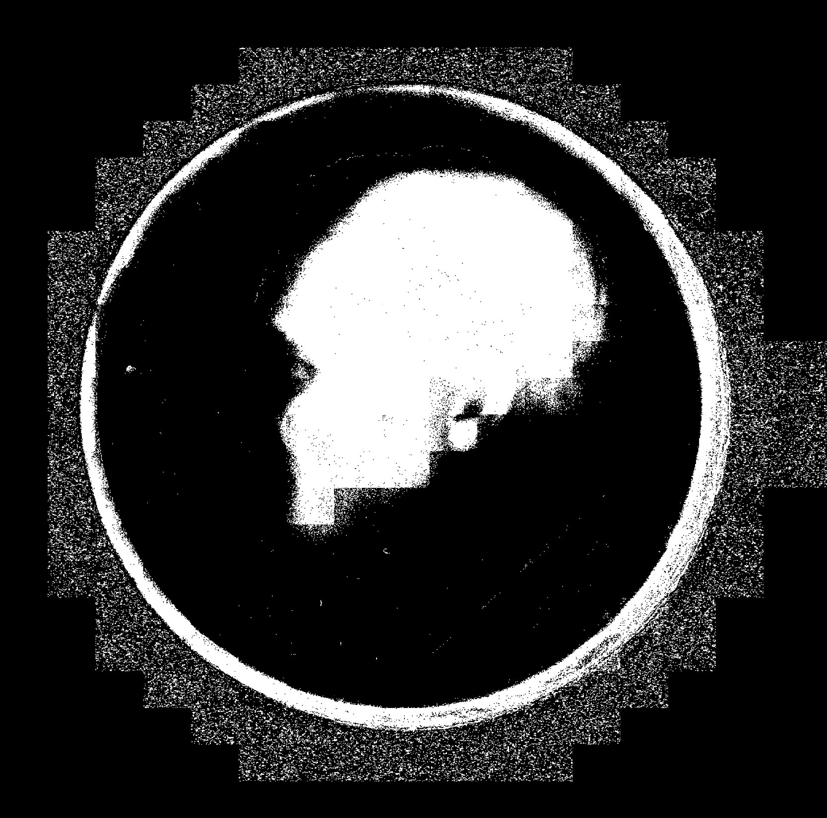
THAT LOOKS BETTER. Omg omg omg omg. It was 2 am and I couldn't sleep. I had to try running it again with even smaller chunks. AND THEN IT LOOKED EVEN BETTER!
WAGA! I dreamt that night of depth maps and 3D models combined with color, and applying this to rotating 3D scans too...
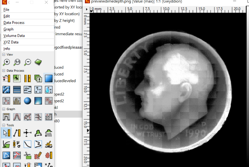
There's still a lot to do with that I'm afraid, but I'll just show you a last couple of things I've been messing around with. I used Gwyddion, meant for atomic force microscope data, and was able to visualize the data and level the plane somewhat, remove the background and stuff like that.
And then it turns out, once you get to this point, getting an STL file is as simple as pretending you're trying to make a lithophane. I used LithophaneMaker.com because it has the option of cutting out circles:
And there we go. A 3D scan of a dime using a digital microscope, a 3D printer, and a few thousand lines of bad python.
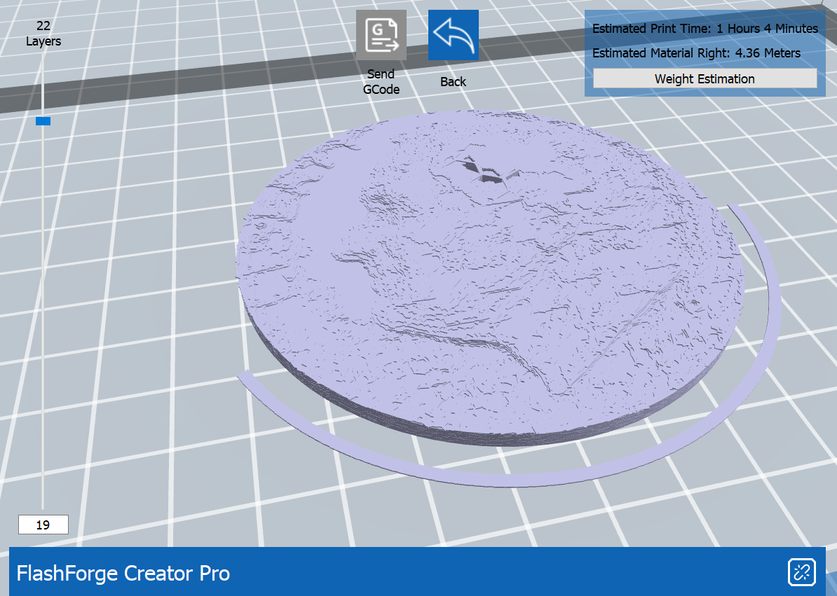
Let's print it!
Edit: I printed it!

Needs some feathering on those mosaic lines. Other than that, though, I'm quite happy with how it turned out! It's really exciting to be able to hold it in your hand and poke roosevelt in the face.
Discussions
Become a Hackaday.io Member
Create an account to leave a comment. Already have an account? Log In.