andreimestereaga
The concept
The idea started few months ago when I had to create a RF node for my farm (I'm growing hazel trees). Because I'm pretty far from my field (about 200 km), I have to work remotely a lot, currently I'm concerned with the monitoring of the area and also I need useful data: soil moisture, air and soil temperature and so on in order to know when to intervene locally and to water the plants (the hazel trees are not pretentious plants, but considering the global warming it's critical to do this when the temperatures are going high).

So I created a RF node which is using the nrf24L01 chip and an AVR microcontroller, then this is connecting with a gateway (raspberry pi + nrf24L01) to establish the internet access. I thought it would be a cool idea to program my modules remotely, so this will allow to update my software without being physically there. That was the moment when I realized that we need a solid software that can fit multiple hardware and provides to the user a proper interface to access the RF communication and also provides support for self programming using the RF communication. Of course one solution is to use NRF5 series which have OTA support (Bluetooth or NFC) and other nice features, but also the price is higher and sometimes we need something light and easy to program or use especially when your code is wrote for AVR microcontrollers (anyway, I can integrate the NRF5 hardware in my software too).
Kickoff
We started to work in November 2019, the team name is CodingNight (each of us is working 8 hours per day as software engineers, so any free time is in the evening when we crack open few beers while coding). The first goal was to make a concept proof of this software, so the main functionality was the OTA update. To achieve this we started to write the bootloader and nrf24L01 radio library, also I had to create a working environment for AVR - we're using the Atmel Studio 7 for development and our current hardware is a ATmega16 microcontroller.
Concept proof
The first thing was to define the flash layout, so considering that our microcontroller has just 16kB of memory and the maximum BLS size is 2kB, we had to find a way to fit the radio library in this small space - it was very hard to have a minimal working library and also a functional bootloader in this given space. The solution was to use the user space for the radio library, then we thought that the same code can be used by the user application as well, why to duplicate some code in flash memory when we can share this between the bootloader and the application? Yes, this will affect the robustness of the bootloader, in practice the bootloader should be a small piece of program that is well written and it doesn't require frequent updates and the most important, it should't malfunction, considering that it is a very basic functionality of the microcontroller. In spite of this, we still considered that it worth to create this bootloader because later we can add some functionality to prevent problems (some recovery code to a stable version, etc). Also this will reduce the bootloader size, we still use 2kB for the development, but our intention is to reduce the BLS size in the feature.
Memory layout
After I finished the radio library implementation - I tried to keep it as light I could but it still resulted in almost 3.2kB of code using O1 optimization - finally I was able to define the flash layout for the ATmega16, and it looks like this:
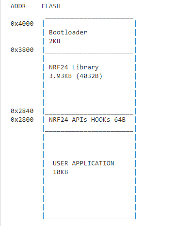
Currently we're using 2kB just for self programming APIs, initialization code for radio library and flashing routine - the hand-shacking protocol between bootloader and flashing tool. The programming tool is a python script that just takes the application HEX file and split it down in radio packages and send it to a specific RF node. The programmer hardware consists of a RF node and a serial to USB device, so this allow you to run the python script from Linux / Windows.
I allocated 4kB for radio library and I placed this in user space - the BLS section is defined by microcontroller's fuse bits, so the current configuration is using the 2kB BLS starting with 0x3800 address (byte addressable, but in fuse settings the address is word addressable so actually 0x3800 is 0x1C00). The radio library is starting at 0x2840 address, so this means there are ~10kB left for user application. The flashing tool is responsible to check if the application that will be flashed can fit this space.
Firmware vs Application
Because I want to compile the bootloader alongside the radio library and the application separately as a standalone project, then I had to use pointers to access the radio APIs from application since the application doesn't have access to these APIs directly. As result, the bootloader and radio library are going together and this is the firmware image (the hex program which is initially flashed on microcontroller - I'm using the Usbasp programmer for this job), then the application is the program that will be uploaded to the target using the flashing tool (developed by us in python) through radio packets.
Hooks
The application can access the radio APIs using the hooks that are defined at 0x2800 address. This section is a table of entry points for each radio API that is located in the firmware image. So this means that radio implementation is completely hidden from the user and this increase the radio hardware abstraction.
In this scenario, the firmware code is compiled separated than the user code, that means the linker will shift the radio functions automatically based on optimization level or other settings, then with each change in the radio library or in the bootloader, the user has to get a new list of addresses of the radio functions, in practice this is not something that you want to do. So instead of doing this, I created a table that contains the addresses of the radio functions and this is populated when the firmware is compiled and linked e.g:
fptr_t ptrs[] __attribute__((used, section(".radio_fptrs"))) = {
    (fptr_t)nrfRadio_Main,          //OFFSET is zero, the address is NRF_LIB_HOOKS_BASE_ADDR + 0
    (fptr_t)nrfRadio_TransmitMode,  //OFFSET is 2, the address is NRF_LIB_HOOKS_BASE_ADDR + 2
    (fptr_t)nrfRadio_Init,          //OFFSET is 4, the address is NRF_LIB_HOOKS_BASE_ADDR + 4
The above array is placed in .radio_fptrs section which starts at 0x2800 (and this is set in linker options tab and passed down to the toolchain). When the firmware is changed and if any radio function is shifted, then the table will be updated accordingly. The user has only to know where is this table in memory - in this case it is defined at 0x2800 - then it can call any API using pointers. To facilitate the whole process, I created a .c file that contains these pointers e.g:
radio_error_code (* const __flash *fptr_nrfRadio_Main)(radio_context *) = (radio_error_code(* const __flash *)(radio_context *))NRF_LIB_HOOKS_BASE_ADDR;
To simplify this even more, also I created a wrapper around these pointers (defined in a header file) and the radio instance - currently the hardware and software supports only one radio instance, therefor is no need to let the user to manage the radio instance variable since this is kind of singleton implementation, I'll explain this later - e.g:
extern radio_context _radio_instance;
extern radio_error_code (* const __flash *fptr_nrfRadio_Main)(radio_context *);
//**************************
// The main routine of Radio library which is used to handle the asynchronous operations
// Method:    __nrfRadio_Main
// Returns:    radio_error_code
//**************************
#define __nrfRadio_Main() (*fptr_nrfRadio_Main)(&_radio_instance)
So the only thing to worry about is to know what is doing __nrfRadio_Main and where to use this, or what parameters you have to pass here, no pointers or instances because makes no sense for user to figure out how the whole thing is working.
As you can see, I have here some constrains, in this case I have a fixed address for each section: bootloader, radio, hooks and user application. These will be defined based on the used hardware, so if I'm going to use an ATmega328p microcontroller, which has 32kB flash, then I have to define another flash layout. The idea is to have a kind of file where I can put the hardware defines like used GPIO, interrupts, memory sections and so on, then based on this I can reconfigure the hardware layer resulting a new firmware image for that hardware, but the user application should remain unchanged - currently I'm still working on this task, the existing code doesn't allow this abstraction yet, but it was made just to have a concept proof for this project.
Radio instance
Previously I mentioned something about radio instance, this is required because the radio library is using some RAM memory for global variables - I need few variables to keep track over some parameters that are required to assure the correct functionality of nrf24 radio (e.g radio state, interrupt status, the nrf24L01 is using an interrupt pin to notify the TX/RX status. Because the firmware, including the radio library, is compiled and linked separately, any global variable in my radio library will be overwritten by the user application's global variables. One solution to prevent this is to shift the whole RAM space in the user application with few bytes (e.g 32B that are required by radio library). This can be achieved with a combination of linker flags on both sides, user application and firmware, but personally I find this solution very difficult to be applied in practice. Also each hardware change may impact the user configuration, which is opposite of what I want to do - to make things easier for the user. The solution was to declare a radio instance in the user application, then this is passed to any radio APIs - if you remember, previously I mentioned a .c file where I defined some pointers, so the radio instance is declared here as well e.g.:
radio_context _radio_instance = {0};
In this way the radio library will get access to this memory through a pointer - the radio instance is passed as an argument for each API call - so we don't have to worry about the memory conflicts between the user application and the firmware.
Interrupt routine implementation
Another thing is the interrupt routine, this is the external interrupt 0 ( INT0_vect) and is used to notify the RX / TX status of nrf24L01 module. This have to be used by both, bootloader and user application. If this routine is compiled by firmware project, then this will update the interrupts vector table with your routine's address and it is placed at the beginning of the compiled code - for the bootloader this is the 0x3800 address. For the user application, we have somehow to update its interrupts vector table and to put the routine's address (compiled by the firmware) at the correct position - INT0 entry.
The first problem is that it's really difficult to use the current AVR interrupt library for this job (not sure, but it may be impossible), there is no APIs that allows you just to specify the address of your interrupt routine - otherwise, I think, this can be achieved with a combination of linker settings, but to be honest it's simpler just to alter the resulted hex file of application adding the interrupt routine's address in the interrupt vector table, or you can do this using a python script, actually the flashing tool can do this job for you. The second problem is that the linker can shift this interrupt routine, so after each firmware change, somehow I have to extract the newest address of this routine and then to use it to update the user application program. Of course, none of these solutions are feasible.
But is there a way to share somehow this interrupt routine between the bootloader and the user application? Yes, the answer is the .c file where I placed the definition of the radio APIs and the radio instance variable. The interrupt routine is a simple and short piece of code - it just saves few flags globally that are required by radio library and also it sends a SPI command in order to clear the interrupt flags into the radio module, so then this routine can be easily compiled by the user application and so well by the bootloader, then the interrupt table will be updated accordingly for both cases.
In the end, I got a .c file that is shared between the application and the firmware - I named this file as nrf24Radio_shared.c - and this contains around 60 lines of code, so it is really light and it doesn't have so many dependencies - just the nrf24 public headers and few SPI defines because the interrupt routine has to access the SPI driver, I think this is a good compromise. It looks like this:
...
radio_error_code (* const __flash *fptr_nrfRadio_LoadAckPayload)(radio_context *, radio_pipe, uint8_t*, uint8_t) = (radio_error_code(* const __flash *)(radio_context *, radio_pipe, uint8_t*, uint8_t))(NRF_LIB_HOOKS_BASE_ADDR + 28);

//the instance that is used to store the radio details (states, pipes configuration and so on)
radio_context _radio_instance = {0};

#define _SPI_WAIT()              while ((SPSR & _BV(SPIF)) == 0)
#define _SPI_LOAD(byte)            SPDR = byte
#define _SPI_DATA                SPDR

ISR(IRQ_HANDLER)
{
    GIFR = (1<<INTF0);
    _radio_instance.irq_triggered++;
    CSN_LOW();
    //load status
    _SPI_LOAD(NOP);
    _SPI_WAIT();
    _radio_instance.irq_status = _SPI_DATA;
    CSN_HIGH();


    CSN_LOW();
    //clear interrupt
    _SPI_LOAD(W_REGISTER | (REGISTER_MASK & STATUS));
    _SPI_WAIT();
    _SPI_LOAD( (uint8_t)(_BV(RX_DR) | _BV(TX_DS) | _BV(MAX_RT)) );
    _SPI_WAIT();

    CSN_HIGH();
}
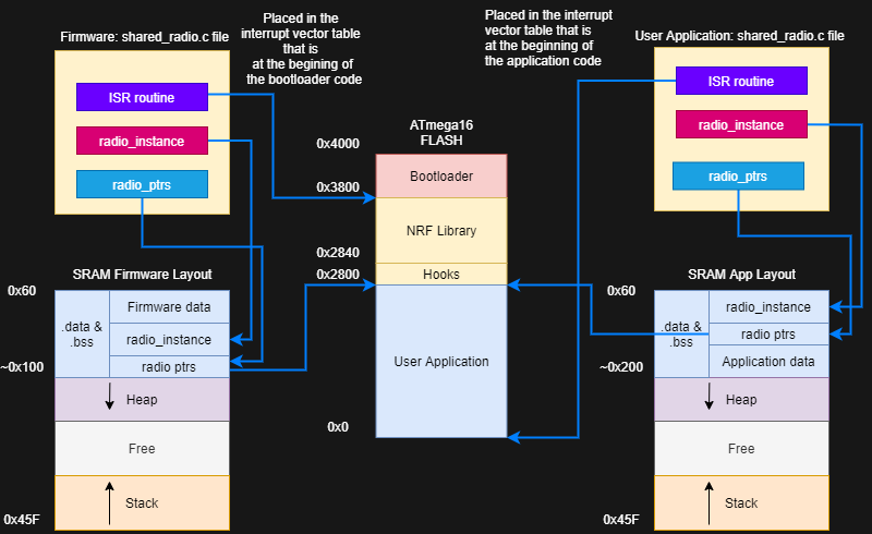
Memory layout Overview
To sum up, I created a diagram where you can check the flash / RAM memory layout and how these are shared between application and firmware.
OTA mechanism
Unlike other bootloaders, one reset on target is not enough to put it in the programming mode. We are using the eeprom memory where is defined a download flag, so each time the target restarts, the flag is checked and if this is enabled, then it enters in the download procedure so then the programmer is allowed to send the program data over wireless. When the transfer is completed and the checksum is correct, then the target will unset the download flag, then it will do a watchdog reset - to be sure that we don't let some SFR registers uninitialized. If the download procedure fails, then the target will do also a watchdog reset, so the procedure can be restarted.
Another thing is that once the download flag is set, the target will remain in bootloader until a new program is received and validated. Of course, we need an application that knows how to handle the download flag. Also in the application we'll check if the update request is secure: this goal of this software is to upgrade your application to a newer version which is genuine, so in this way we can add some security features to the application like:
- Configurable application secret key (encrypted with AES)
- Downgrade is not allowed unless the software is compiled in debug mode
The idea is that the user has to develop an application which is compatible with this firmware, so in this case I'll add support for application development: configurable files and templates or examples that can be easily integrated in any user application.
Below is a diagram that describes how this mechanism is working:

Hardware
I discussed a lot about software, but of course, we also developed some hardware for this project, actually the application requires just an atmega16 and a nrf24L01 chip, so you don't have to build something from scratch as we did, any board that has an atmega16 and a cheap nrf24L01 module are enough (be careful with the clones, I had also problems with these, some of nrf24 doesn't work well).
V1 Board
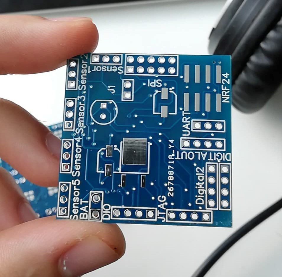
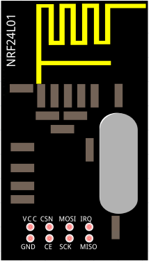
So we started with v1 hardware development. This is a 40x40 mm board which contains the microcontroller (atmega16), the DC regulator (we need 3V3 line on board to power up the nrf24L01 chip alongside the microcontroller, the main power input for the module is a standard 9V battery), header connectors and a resistor divider network (required for the analog sensors). The nrf24L01 is plugged in this board using a standard 2x4x2.54 female header which is matching the common nrf24L01 pinout, as below:
The schematic is available in this project (check v1_board.pdf ), but if you are a AVR fan, it is really easy to do your own hardware using just a microcontroller, a nrf24L01 module, a breadboard and few wires, then you can flash the firmware using any AVR programmer that supports atmega16. There are just basic connections between the microcontroller and nrf24L01 module through the SPI interface. Also if your nrf24L01 module doesn't have a buildin regulator, just be careful at your input voltage: this have to be at most 3.5V, but 3.3V is widely recommended (if it is less than 3.3V, the module is still working well but the communication range is negatively impacted).
In my case, I preferred to do my own PCBs, so after I placed the order and few weeks passed, the result was really satisfactory, check below a picture of one of these modules: