 Paul Gould
Still helping u/_jeem_
Syncronising the start pulses
Half bridge MOSFET control and avoiding shoot through
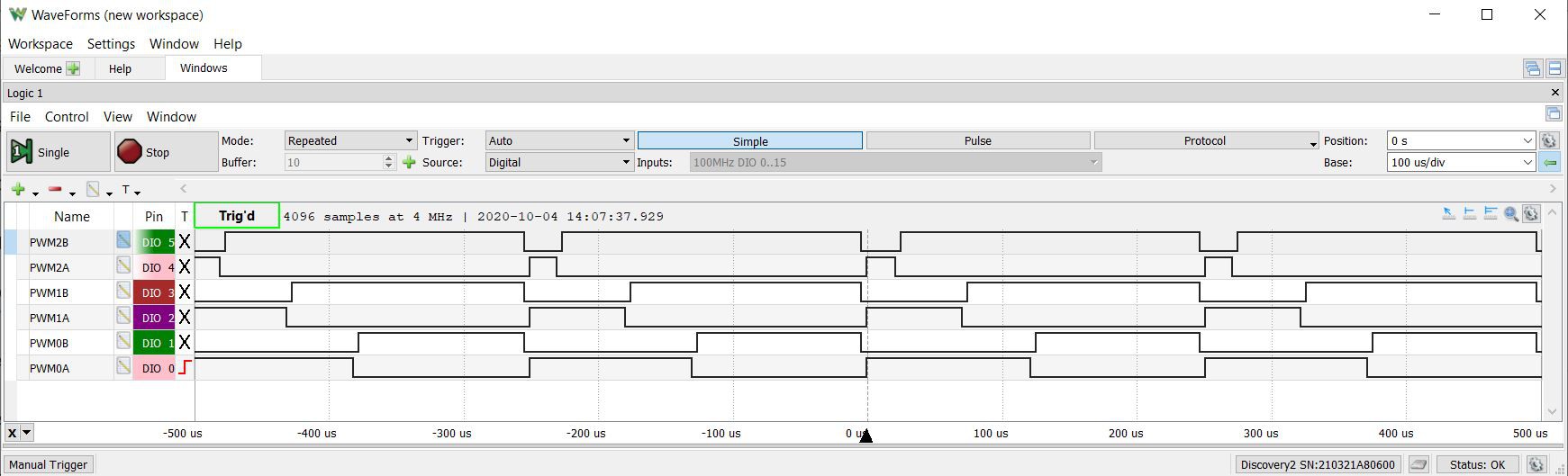
PWMxA is the highside FET
PWMxB is the lowside FET
High = FET on
#include "driver/mcpwm.h"
#include "soc/mcpwm_reg.h"
#include "soc/mcpwm_struct.h"
#include "wiring_private.h" // pinPeripheral() function

// MCPWM Pins
#define GPIO_PWM0A_OUT 15   //Set GPIO 15 as PWM0A
#define GPIO_PWM0B_OUT 02   //Set GPIO 02 as PWM0B
#define GPIO_PWM1A_OUT 0   //Set GPIO 00 as PWM1A
#define GPIO_PWM1B_OUT 04   //Set GPIO 04 as PWM1B
#define GPIO_PWM2A_OUT 16   //Set GPIO 16 as PWM2A
#define GPIO_PWM2B_OUT 17   //Set GPIO 17 as PWM2B

static void setup_mcpwm_pins()
{
    Serial.println("initializing mcpwm control gpio...n");
    mcpwm_gpio_init(MCPWM_UNIT_0, MCPWM0A, GPIO_PWM0A_OUT);
    mcpwm_gpio_init(MCPWM_UNIT_0, MCPWM0B, GPIO_PWM0B_OUT);
    mcpwm_gpio_init(MCPWM_UNIT_0, MCPWM1A, GPIO_PWM1A_OUT);
    mcpwm_gpio_init(MCPWM_UNIT_0, MCPWM1B, GPIO_PWM1B_OUT);
    mcpwm_gpio_init(MCPWM_UNIT_0, MCPWM2A, GPIO_PWM2A_OUT);
    mcpwm_gpio_init(MCPWM_UNIT_0, MCPWM2B, GPIO_PWM2B_OUT);
} // setup_pins()

static void setup_mcpwm()
{
   setup_mcpwm_pins();

   mcpwm_config_t pwm_config;
   pwm_config.frequency = 4000;  //frequency = 20000Hz
   pwm_config.cmpr_a = 50.0;      //duty cycle of PWMxA = 50.0%
   pwm_config.cmpr_b = 50.0;      //duty cycle of PWMxB = 50.0%
   pwm_config.counter_mode = MCPWM_UP_COUNTER; //MCPWM_UP_DOWN_COUNTER; // Up-down counter (triangle wave)
   pwm_config.duty_mode = MCPWM_DUTY_MODE_0; // Active HIGH
   mcpwm_init(MCPWM_UNIT_0, MCPWM_TIMER_0, &pwm_config);    //Configure PWM0A & PWM0B with above settings
   mcpwm_init(MCPWM_UNIT_0, MCPWM_TIMER_1, &pwm_config);    //Configure PWM0A & PWM0B with above settings
   mcpwm_init(MCPWM_UNIT_0, MCPWM_TIMER_2, &pwm_config);    //Configure PWM0A & PWM0B with above settings
   mcpwm_deadtime_enable(MCPWM_UNIT_0, MCPWM_TIMER_0, MCPWM_ACTIVE_HIGH_COMPLIMENT_MODE, 40, 40);
   mcpwm_deadtime_enable(MCPWM_UNIT_0, MCPWM_TIMER_1, MCPWM_ACTIVE_HIGH_COMPLIMENT_MODE, 40, 40);
   mcpwm_deadtime_enable(MCPWM_UNIT_0, MCPWM_TIMER_2, MCPWM_ACTIVE_HIGH_COMPLIMENT_MODE, 40, 40);

   mcpwm_sync_enable(MCPWM_UNIT_0, MCPWM_TIMER_0, MCPWM_SELECT_SYNC_INT0, 0);
   mcpwm_sync_enable(MCPWM_UNIT_0, MCPWM_TIMER_1, MCPWM_SELECT_SYNC_INT0, 0);
   mcpwm_sync_enable(MCPWM_UNIT_0, MCPWM_TIMER_2, MCPWM_SELECT_SYNC_INT0, 0);

   MCPWM0.timer[0].sync.out_sel = 1;
   delayMicroseconds(1000);
   MCPWM0.timer[0].sync.out_sel = 0;

   int pwm0 = 50;
   int pwm1 = 30;
   int pwm2 = 10;
   mcpwm_set_duty(MCPWM_UNIT_0, MCPWM_TIMER_0, MCPWM_OPR_A, pwm0);
   mcpwm_set_duty(MCPWM_UNIT_0, MCPWM_TIMER_0, MCPWM_OPR_B, pwm0);
   mcpwm_set_duty(MCPWM_UNIT_0, MCPWM_TIMER_1, MCPWM_OPR_A, pwm1);
   mcpwm_set_duty(MCPWM_UNIT_0, MCPWM_TIMER_1, MCPWM_OPR_B, pwm1);
   mcpwm_set_duty(MCPWM_UNIT_0, MCPWM_TIMER_2, MCPWM_OPR_A, pwm2);
   mcpwm_set_duty(MCPWM_UNIT_0, MCPWM_TIMER_2, MCPWM_OPR_B, pwm2);
} // setup_mcpwm

void setup() {
  setup_mcpwm();
}

void loop() {
}
This is not ideal as I still have to set the duty cycle for both PWMxA and PWMxB and this could be prone to errors.
I would like to use PWMxA only
I thought that
MCPWM_ACTIVE_RED_FED_FROM_PWMXA
or
MCPWM_ACTIVE_RED_FED_FROM_PWMXB
would work correctly but it does not.
Discussions
Become a Hackaday.io Member
Create an account to leave a comment. Already have an account? Log In.