 Jeff Cooper
Last week, the PCBs for the project arrived, as well as the missing box of components from digikey (delivered by a friendly neighbor whom I'd never met... I don't know which house is his, but it isn't anywhere near mine). I started putting them together Thursday evening.
First up was the USB breakout board, which went swimmingly
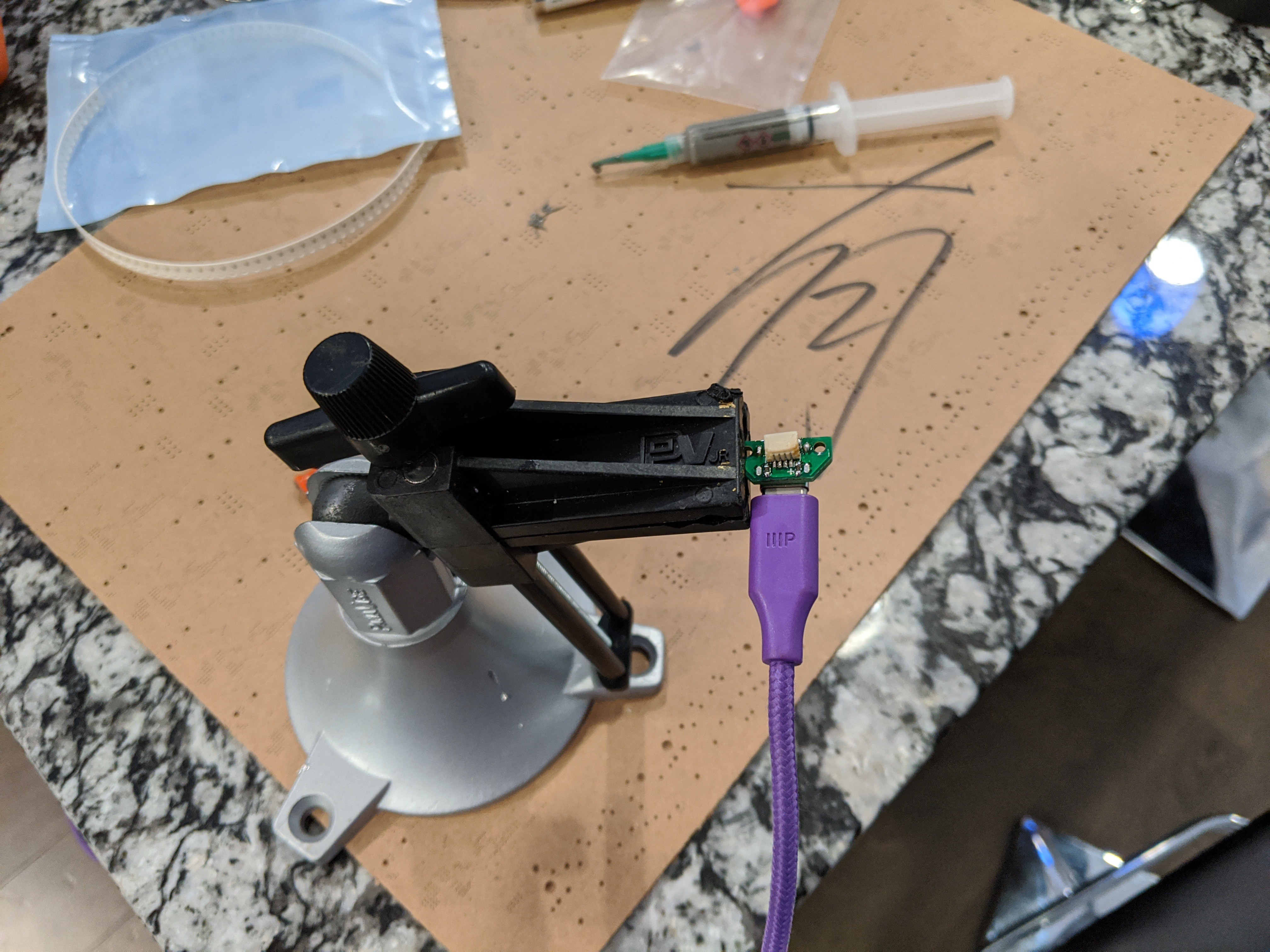
The USB board is super simple, so I didn't really expect any issues with it. However, it was nice confirmation that sometimes, things do work on the first try. I was successfully getting 5v from a USB-C plug.
Next up I moved on to the power management board, which is where I started to run into problems.
First, I discovered that I forgot to order the JST-PH battery connector and the fuel gauge IC. Neither of these was a huge deal for testing, so I soldiered on.
I put the rest of the board together, only managing to fling two battery charging ICs out of my tweezers and into the void, and, after a few quick sanity checks, did what any overly-optimistic hacker would do: I plugged it in.
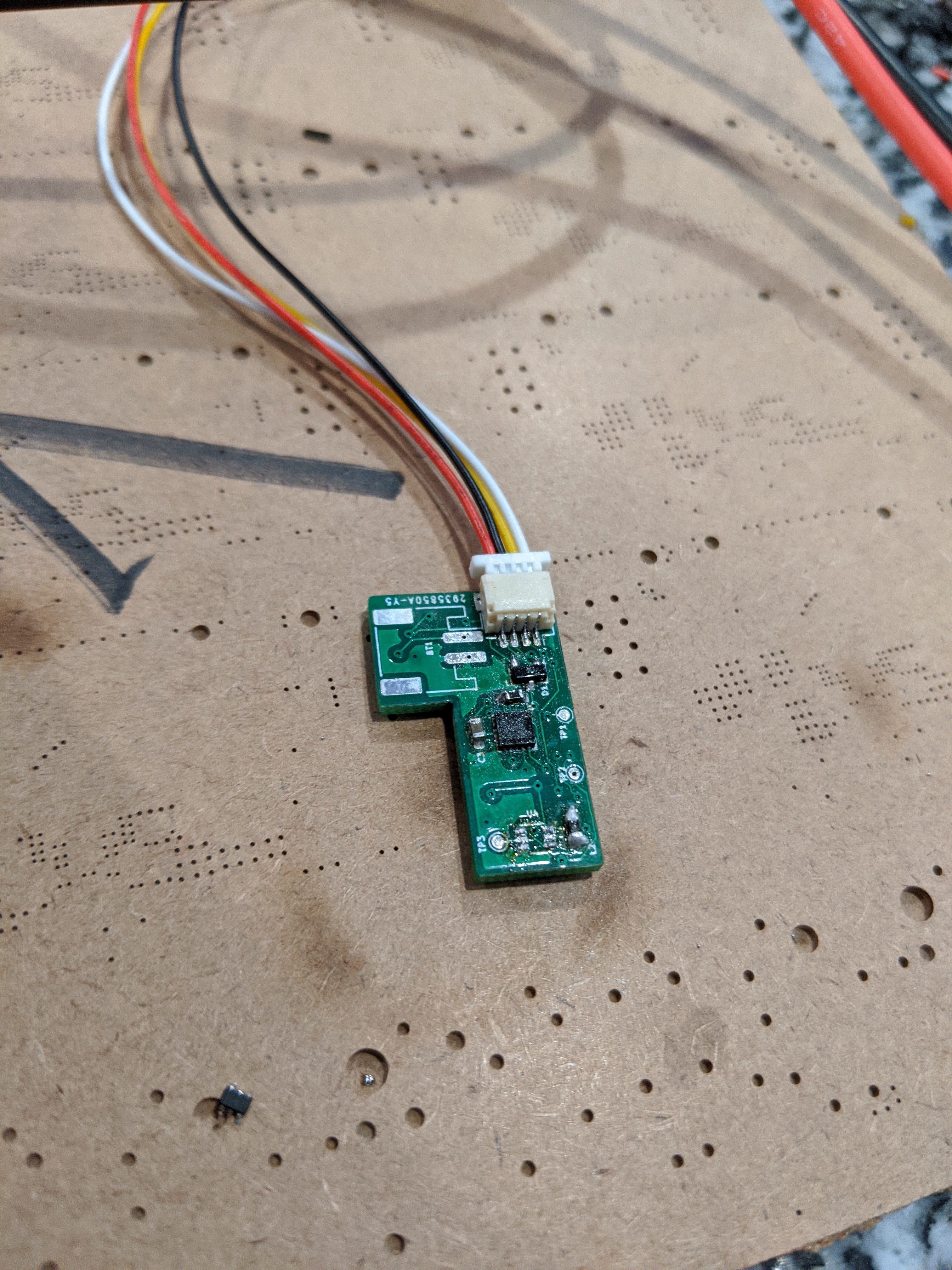
The first thing I noticed was the familiar smell of magic smoke, which turned out to be coming from the battery charging IC. I quickly unplugged the board and desoldered that IC (which now had a suspicious bulge). I double-checked my schematics against the reference for those parts and couldn't find anything amiss, so I started looking for other potential causes.
This is where things got a little weird. According to my test points (which, protip, don't forget to include a test point for ground!), my +5v net was indeed getting +5v, at a slightly different voltage (if I remember correctly, a higher voltage) than the input from USB. My +3.3v net was... also getting +5v, but at yet a third slightly different voltage. I double- and triple-checked my schematic and tested the board for shorts. There was no short between any of VIN, +5V, or +3.3V, yet all of them were reading close to 5 volts. Unfortunately, around this point I ran out of time to debug and had to put the project away. I've been out of town ever since, wondering what could possibly be going on but with no way to test any hypotheses. I'm wondering if I either shorted something on the QFN 3v3 regulator (distinctly possible), or if I somehow ended up with the 5v version of that same regulator (this seems unlikely...). I'll be able to play with it more when I'm back in town next week.
In an unrelated thought, I've still been straining to think up a use case for a connected smartwatch that I would actually take advantage of. The only one I can think of is home automation control, so I've been brainstorming other ways this might be possible. If I can make a solution work with infrared or LoRA control, I can switch from the nrf52 to something like an STM32, which could potentially be even lower power. The nice thing about my design is that doing this wouldn't require a total rework of the project: the power, USB, and button boards would all be the same. Only the logic board would have to change. I may end up doing this anyways at some point, even if I keep the nrf52.
Discussions
Become a Hackaday.io Member
Create an account to leave a comment. Already have an account? Log In.