 Jeff Cooper
What's wrong with this picture?
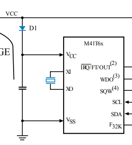
If you answered "nothing," you're absolutely right. It's taken directly from the M41T6x Datasheet, and my schematic has a an identical block (minus the crystal, which is embedded in the LCC package that I'm using):
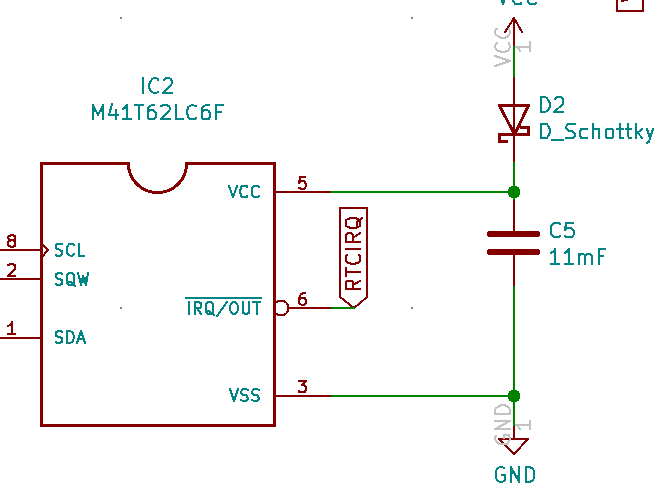
Now, what if I told you that, when I soldered in the 11mF supercapacitor and plugged it in, I measured voltage across it higher than VCC. Significantly higher, actually: VCC on this board is 2.8V, but after leaving the circuit plugged in for a while, I measured 3.2V (and climbing, in spurts every few seconds) across the capacitor. So what's wrong? Well, let's look at where VCC comes from:
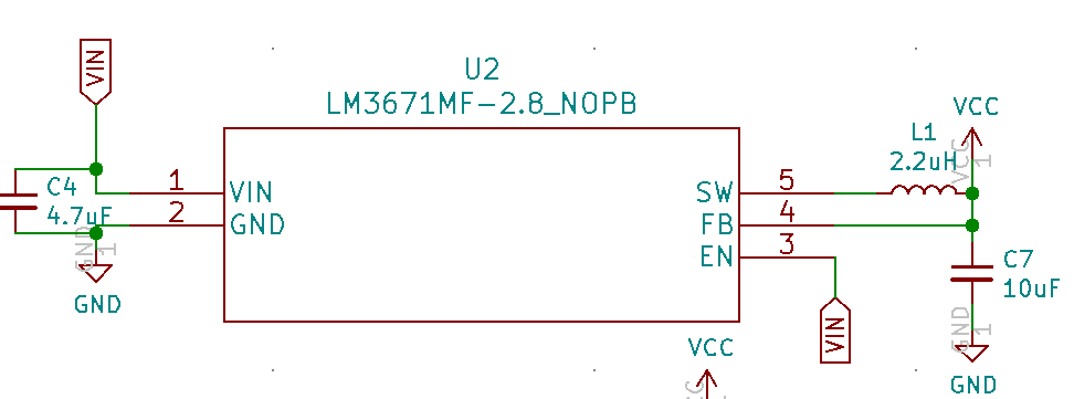
Again, nothing special. This schematic, including all of the component values, is taken directly from the LM3671MF datasheet. But let's look at a simplified version of the circuit they form together:
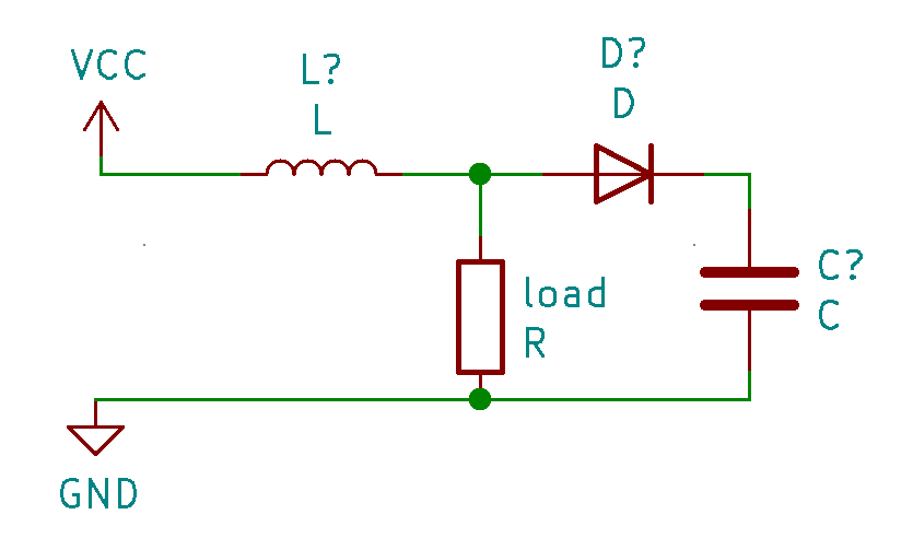
Here, the resistor stands in for the load provided by the MCU and other various components. If you have a background in electronics (and I don't, so hopefully someone in the comments will correct the mistakes I inevitably make), you might also recognize this as very similar to the layout of a boost converter: if you replace the load resistor here with a switch and rapidly open and close it, current will build up across the inductor when the switch is closed, then be forced through the diode into the capacitor when the switch is open. By repeating this process faster than the capacitor discharges (through leakage or load), the voltage across the capacitor can get much higher than VCC.
Now, when we look back at our original circuit, the behavior I saw starts to make a bit more sense. The program running on the microcontroller periodically reads from the RTC module via the (hardware) I2C bus, and then prints the results to a serial terminal (via onboard USB), then sleeps for a few seconds. The MCU draws more current when it's working than when it's sleeping, so the current being drawn through the inductor goes up. When the MCU goes back to sleep and suddenly draws less current, the current flows through the diode and into the capacitor, just like in a boost circuit. The feedback pin on the 2.8V regulator is before the diode, so the regulator is oblivious to problem. This explains the spurts of voltage increase that I saw on the multimeter (I don't own an oscilloscope, otherwise I'd have cool graphs attached to this post). Luckily I noticed this before the voltage got so high that it burned out any components.
So what do we do about this? The supercapacitor is in the circuit to act as a backup for the RTC, so that it can keep time when the battery is disconnected or runs out. While I could do something like put in a second regulator on the RTC-side of the diode just to charge the capacitor (bypassing VCC entirely), the simplest solution is the best one here: just remove this part of the circuit. An RTC backup is a "nice-to-have" feature, but this is a smartwatch: when power is reapplied, it can just get the time directly from the paired smartphone. The RTC module has functionality to detect when it has lost power (the "oscillator fail" bit), so it should be easy to know when a resync is necessary.
Thankfully, the current revision of the board is perfectly workable with the capacitor simply removed. The next revision won't include it (an 11mF supercap has a pretty large footprint). I do plan on adding a BMA400 accelerometer, though, which has a built-in step counter and tap detection. On top of that, it has this lovely trailer video that makes me wish more companies made trailers for their ICs.
The new 5V regulators won't be here until Mondayish, so I probably won't have a fully-working demo to post about until at least then. I also haven't tested any of the buttons (I'm confident those will work) or light circuits (I'm less confident...), but hopefully I can do that this weekend.
Discussions
Become a Hackaday.io Member
Create an account to leave a comment. Already have an account? Log In.