 Michael Gardi
Motivation
So why would I want to undertake an H-500 Computer Lab reproduction? Because most of the projects that I have been working on lately follow the same pattern:
- They are reproductions of cool computer toys and devices from the 60's.
- Have tremendous educational value (when first released and even now IMHO). To that end they usually shipped with well written and instructive manuals.
- Feature unique and noteworthy designs.
- Due to their age they have become rare and thus expensive and hard to get.
- Perhaps most importantly I think that the devices themselves and their designers deserve to be remembered and honored.
- As a bonus for this particular project, I'm Canadian and the H-500s were manufactured in Canada.
So the H-500 is a very good fit for my interests and skill set. Plus I really want one ;-)
Design Goals
With this reproduction I hope to provide the best H-500 Computer Lab experience possible. What do I mean by that? Well...
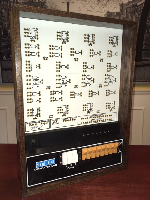
- Visually my reproduction will be clearly recognizable as an H-500. I will strive to provide an outwardly accurate appearance of the original to the best of my ability and within the constraints of the implementing technologies. Bear in mind that I can't afford one of these so I will be working from images and the kindness of actual owners to provide me with details.
- Operationally my H-500 will perform like the original. A user will be able to work through the experiments in the Lab Workbook without change or issues.
- I would like for this project to be easy to well, reproduce. To this end I will only be using 3D printed parts and readily available components and materials.
- I will try to keep the total project cost to a minimum.
- A complete set of instructions, parts list, and STL files will be posted to Instructables at the completion of this project so that others could make one should they choose to.
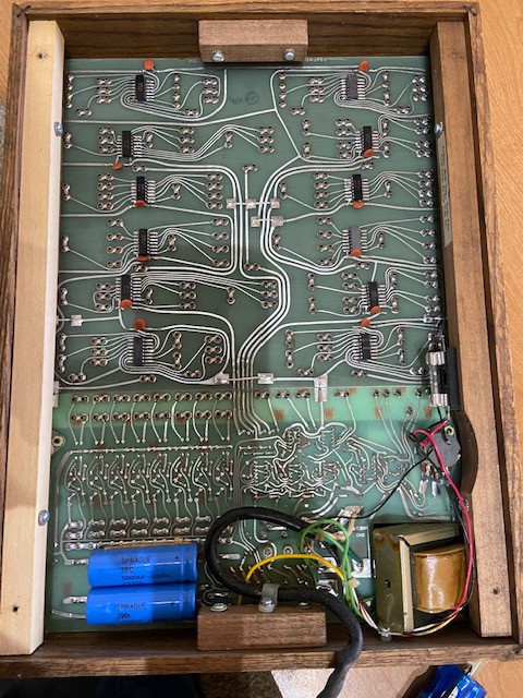
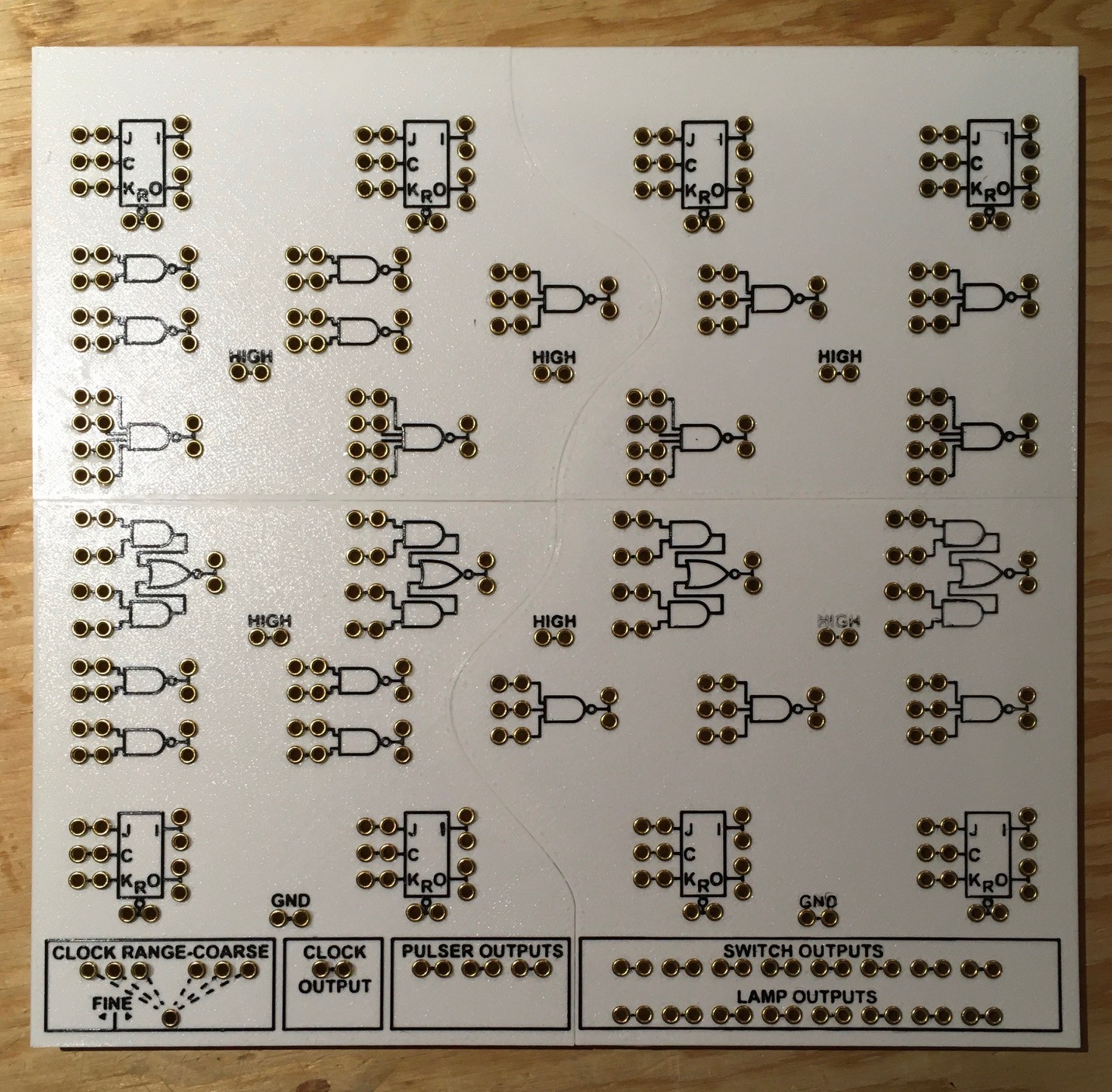
So hopefully my H-500 reproduction will look and work like an original, but I can guarantee (at least for version 1) that the very cool PCB with "surface mounted" components used in the original will not be part of the final design in order to meet cost and reproducibility goals.
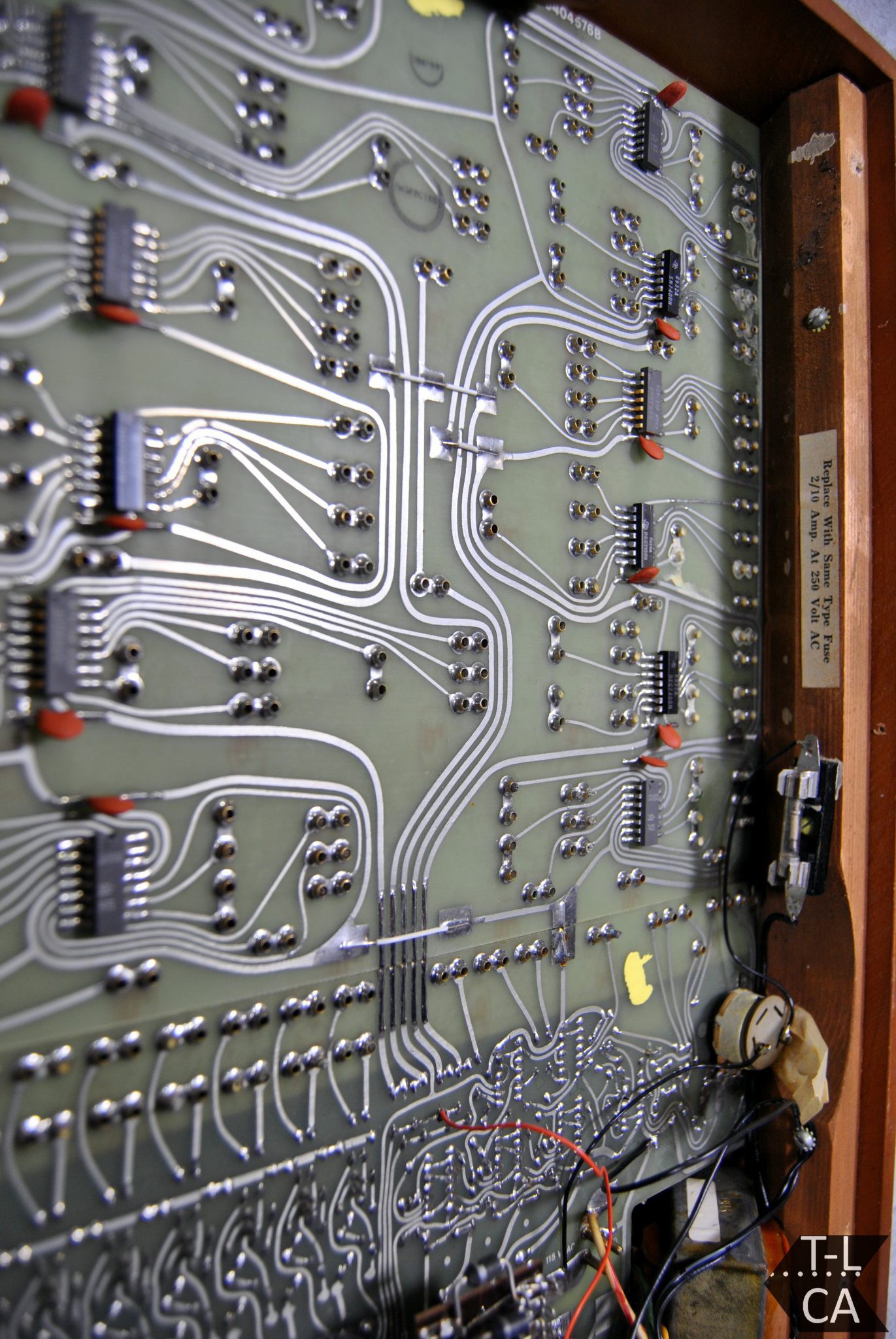
(Maybe version 2?)
Rocker Man
Well rocker switches is actually the reason that I started considering this project. At the end of my Mostly 3D Printed Rocker Switch project I posted the following:
With a workable and customizable rocker switch in my tool kit now, I'm looking at you PDP-8/I ;-)
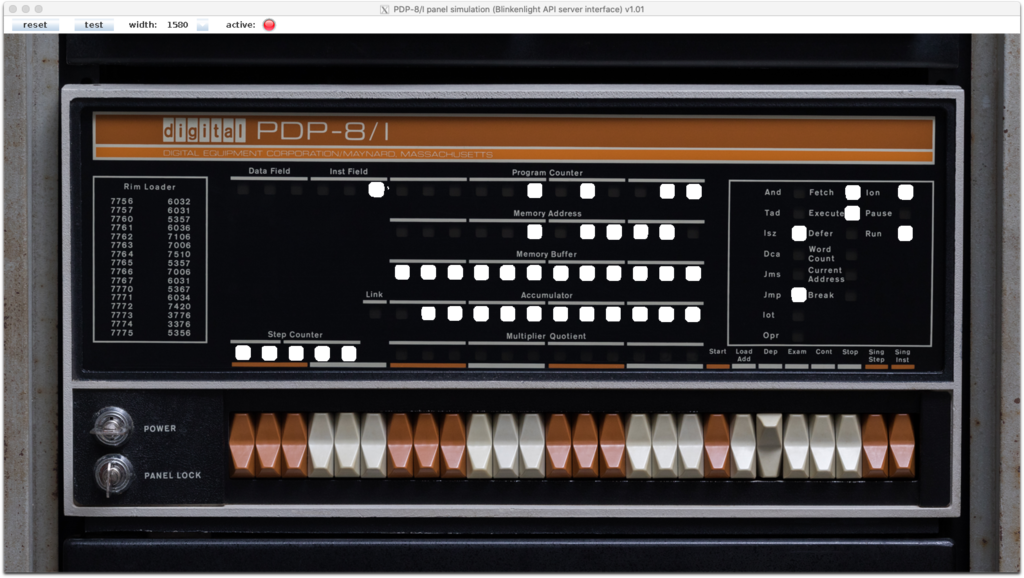 The remark was made somewhat tongue in cheek, but it did get me thinking about it since I love the look of the switches that they used. I actually started researching the possibility of making an 8/I replica. I soon discovered however that Oscarv had already created an awesome 2:3 replica the PiDP-8/I which I purchased (I'm just waiting to finish this project before assembling it). So not much incentive to duplicate his great work.
A short while later I was looking at the System Source Computer Museum Toy Computers page and I saw the DEC Computer Lab. WOW. This was actually a much better fit for both my interests and skill set. I have made replicas of six of the other computer toys on this page five of which I created myself. And the DEC Computer Lab uses the same rocker switches as the PDP 8/I. Perfect.
Making the Switches
My starting point was an STL version of the PDP 8/I rocker switch that I found at Vince Slyngstad's PDP-8 Stuff page.
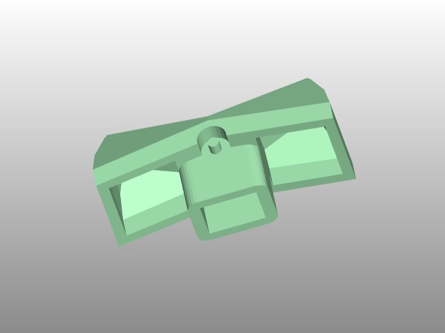
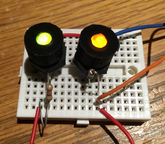
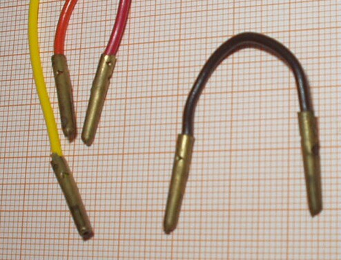
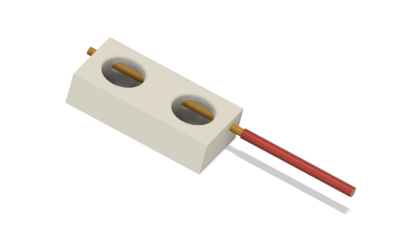
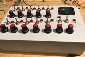
I modified it slightly to have a hole at the pivot point instead of a shaft. Then I modeled a "counter weight" to hold the switch magnets and a corresponding base for the "reciprocating" magnets and the reed switches. You will notice that there are two kinds of counter weights. That's because there are two kinds of rocker switches required, a momentary "spring" return for the three H-500 pulse switches, and an ON-ON variant for the eight input switches.
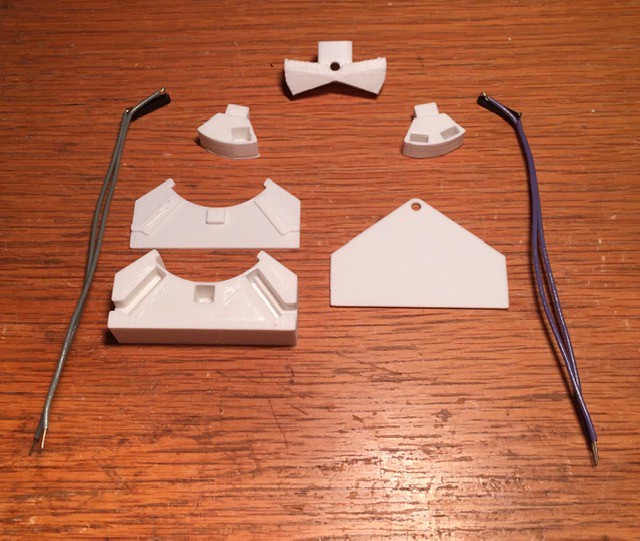
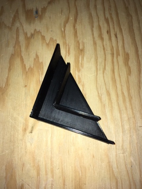
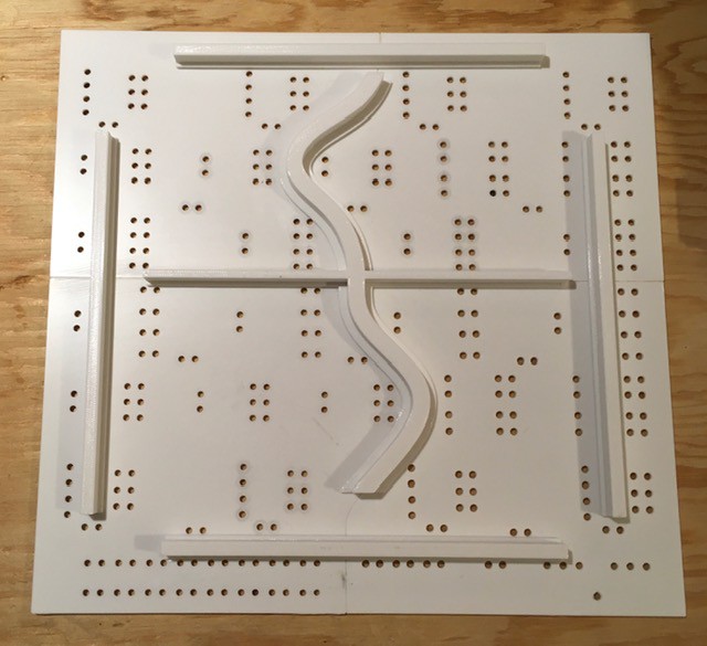
The base has slots...
Read more »


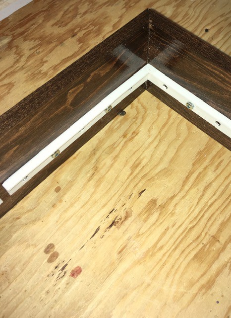
 Once dry I stained the boards then applied a few applications of clear coat. I was a little disappointed in the stain as I was expecting it to be a little lighter and redder like the original's "simulated teak". But given how long it took to get the stain I went ahead and used it.


 Albert Gonzalez
 Walter
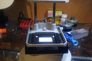
 nullvalue
A guy in UK sells 2 H-500 on Ebay:
https://www.ebay.fr/itm/115811151888
https://www.ebay.fr/itm/115811150665