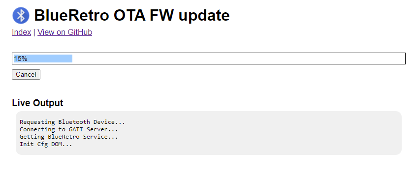
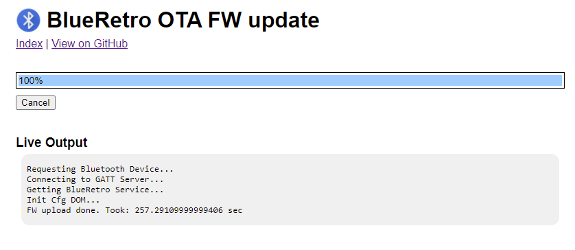
I added OTA FW update with v0.19 release. You got to update to that version first using the USB serial cable method first but when next version is out you will be able to update simply wirelessly via the web-bluetooth interface.
I redesigned how the LED and BOOT switch are used, holding it 3 sec start inquiry scan (and LED start to pulse), short press while inquiry scan is on cancel it (and LED stop glowing), one short press outside of inquiry scan kick out all controllers as before. The LED being solid on still indicate that an error occurred. Holding the switch 10 sec will factory reset the adapter to default config and clear the Bluetooth keys.
I also added the option to disable the automatic inquiry while no controller present via the web config.
I added Atari Jaguar support with version v0.17! Regular pad, 6D controller & TeamTap up to 4 players are supported. Refer to wiki for cable schematic and config documentation.
I wrote my own testing application with JagStudio this time around to test BlueRetro with my GameDrive (especially the 6D controller support). Source and ROM available on GitHub.
I added PC Engine / TG16 support with version v0.16! Regular pad, 6 buttons pad, mouse & multitap up to 5 players are supported. Refer to wiki for cable schematic and config documentation.
Hackaday.io is nice but the more content I add the harder it is to find the older content. You got to click view all project logs and then click next page forever.
Also while it's possible to comment on the log entry, that feature looks to be universally not used here. Also you can't like a log.
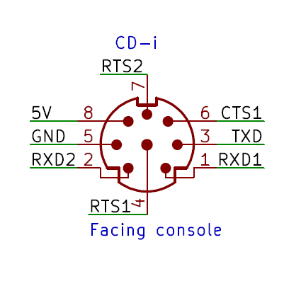
I added CD-i support with version v0.15! Regular pad, mouse & keyboards (K, X & T type) are supported. Any mix of devices is supported for up to 2 players! Refer to wiki for cable schematic and config documentation.
The spec defines RTS and RXD pin as standard RS-232 levels:
- logical 1: -15V < signal level < +0.8V - logical 0: +2.4V < signal level < + 15V
But from what I saw in various schematics the logical 1 level is always 0V and the logical 0 is 5V. So when interfacing with a CD-i interface level shifters are enough (no need for MAX232) as long the UART is configured to be inverted.
Pointing devices like gamepad and mouse defined speed of 1200 & 9600 baud in the original spec but only 1200 devices ever got released. Newer CD-i players dropped 9600 support on the front ports and the latest spec actually removed 9600 as a possible baud rate for mouse and gamepad.
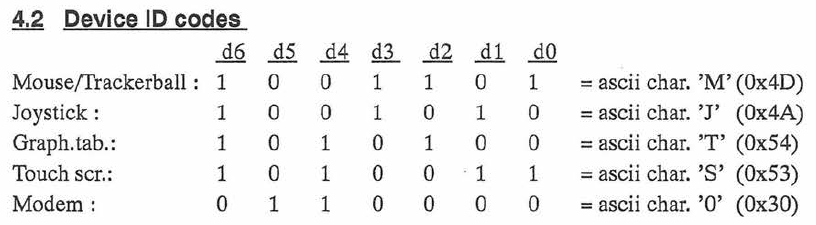
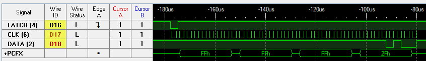
For mouse, gamepad & type 'T' keyboard data signaling is 7 bits with 2 stop bits LSB first. For type 'K' & 'X' keyboards signaling is 8 bits with 1 stop bit LSB first.
Unlike most other game system the CD-i inputs are not polled. As long the RTS line is released devices are free to send data when state change.
Devices are identified once at boot time by holding the RTS line low. Once RTS line is released devices are required to send their 1 byte identification followed by their initial status data.
T is also used for 3rd keyboard type.
This was a problem for BlueRetro as devices per CD-i spec are required to answer the ID request within 500 ms. However BlueRetro take around 700 ms to read its configuration at boot. To work around this BlueRetro need to be powered externally and powered before powering the CD-i. This give the extra time required to load the config and to be ready to answer the ID request.
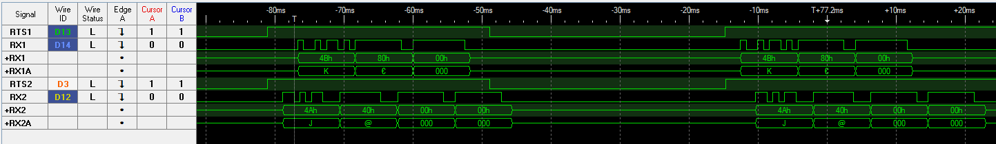
IDs request at boot for gamepad and 'K' keyboard.IDs request at boot for mouse and 'T' keyboard.
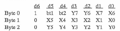
Controller & Mouse
Status update sent on buttons press and release.On axes movements update are continuously sent if value is not neutral (0).
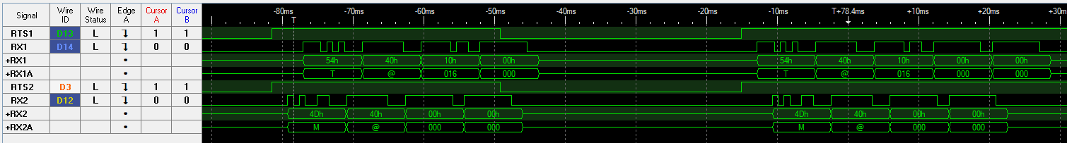
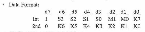
'K' & 'X' type keyboards
Key A pressed and releasedKey A pressed and released while holding shift keyCaps Lock press followed by Key A press and release
'T' type keyboard
Later CD-i model like my CD-i 450 only had a single physical front port including 2 serial port. Only the secondary port was compatible with 8 bits UART configuration that keyboards (K & X) and modem required. This posed a problem for CD online application as this made impossible to use the previous keyboard simultaneously with the modem. To answer this issue Philips defined the 'T' keyboard spec that piggy back on the tablet 'T' ID and redefine the data format to include the same data as the 'K' type keyboard.
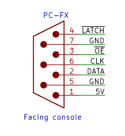
I added PC-FX support with version v0.14! Regular pad and mouse are supported. Any mix of devices is supported for up to 2 players! Refer to wiki for cable schematic and config documentation.
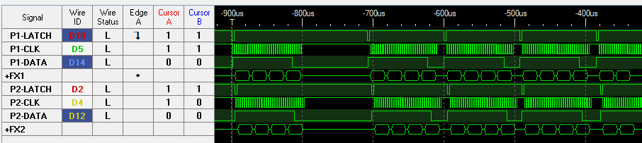
The low level protocol is pretty much like SPI mode 0 for clock and data line. You got the /LATCH line that can be inverted to be use as a CS. An /OE signal can mute the output from the peripheral when high. The console poll the peripherals 5 times in a row every frame. This look like how PC Engine controllers are polled as well for the multitap. Maybe a multitap was plan for the PC-FX as well?
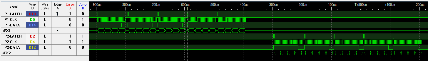
Sequential 2P polling with 5 consecutive poll each
Data line is inverted and LSB is sent first. Clock may sometimes cycle while LATCH is held low, these cycle must be ignored.
Controller poll
The two controllers are often polled simultaneously.
Simultaneous 2P polling
Getting the ESP32 SPI timing was a bit tricky, In my mind this should be SPI Mode 2 but somehow that was very unreliable. Using Mode 0 timing is rock solid however.
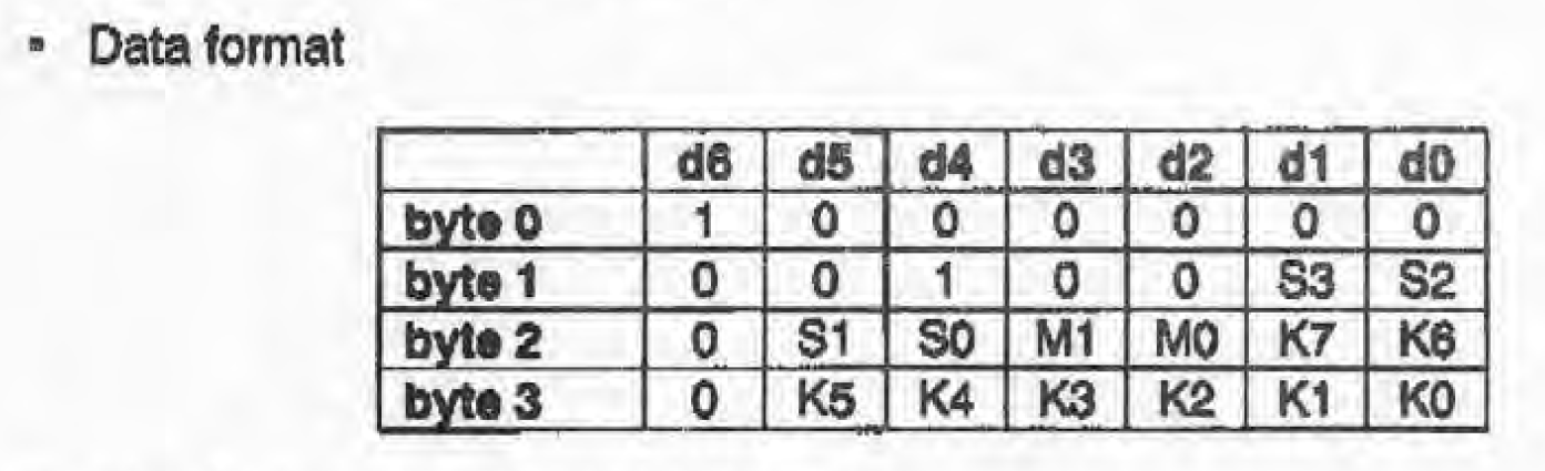
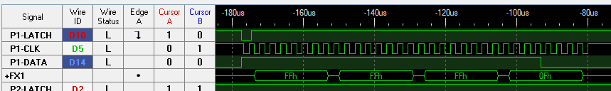
Regular controller
RX: FFFFFF0F (LSB first)
    ││││  ├┘
    ││││  └ ID?
    │││└ Left, Down, Right, Up
    ││└ 1, Mode2, 1, Mode1
    │└ IV, III, II, I
    └ Run, Select, VI, V
 Jacques Gagnon