While the Arduino platform is great for quick-and-dirty prototypes, everyone who has tried knows it is a huge pain to use it for relatively complex prototypes. We know this, and had been considering for a while moving to a more professional HW and firmware design for the microcontroller on the vent. Feedback from some other engineers, testing of the interface with our LCD, and this article all contributed to a fairly large change in the direction of the HW of this project. Instead of using an Adafruit Feather M4 daughter board and the Arduino platform, we moved to an ATSAMD21G18A microcontroller placed on our main PCB. At first glance, it may appear to be an odd choice. We were worried about capabilities and went backwards? The SAMD21 has a Cortex M0+ and runs at a maximum 48MHz. It is effectively the little brother of the SAMD51 with Cortex M4F that the Feather M4 has. However, it turns out that the extra horsepower is really not needed. What is needed is more careful and efficient control of the MCU peripherals which comes from moving away from Arduino.
If there was one picture that could explain the challenge with Arduino, it is the following. The LCD interface is I2C and the LCD does not support a frequency higher than 50kHz. The addressing of characters is not sequential on the LCD, so re-writing the entire screen requires 3 separate I2C transactions to set the 80 characters (4x20) on the LCD character display. Because the I2C speed is so limited, this causes a big challenge. To update the screen every 30ms, the I2C bus is heavily used. This image is of our updated hardware and firmware. The Arduino Wire library has a maximum buffer of 32 bytes, so it actually requires even more transactions!
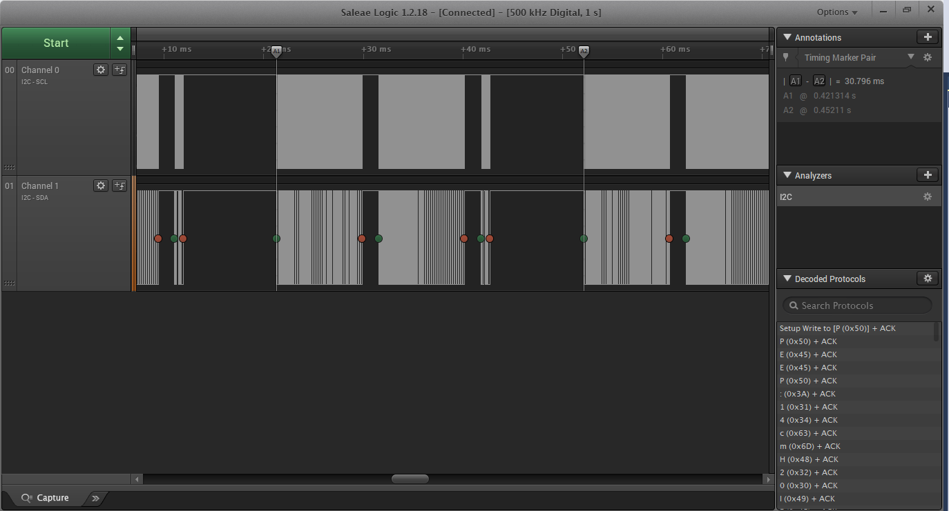
Some more minor optimization could be done, and was done. I modified the firmware to only write any bytes that had changed, and not the entire buffer every time. However, we must consider the worst case, and in that case roughly 2/3 of the time is spent writing to the LCD. Using a blocking I2C driver like Arduino's Wire library, this would be a major challenge, and likely very dangerous. We cannot allow updates to the display to interfere with pressure control of the ventilator. As the linked article above notes, the answer is to use a Real Time Operating System (RTOS), and intelligently use the microcontroller's peripherals to prevent blocking and free up the CPU for other use. If you have never used an RTOS, give it a try. We are using FreeRTOS, one of the more commonly used RTOSs out there. An RTOS gives the developer access to all sorts of useful features such as multitasking (with defined task priorities), software timers, data queues, semaphores, and others which make developing complex systems far easier, faster, and more reliable.
In the case of the ventilator, we have screen buffers for various screens (currently a main and an alarm screen). A software timer switches between the two if any errors are detected. A separate software timer generates the needed I2C transactions to write the screen buffer to the LCD, and adds them to the queue. They are asynchronously pulled from the queue, and handled in the SERCOM I2C peripherals with extremely minimal CPU involvement. What used to be 2/3+ of the total loop time is now a negligible amount, and much easier to develop and understand.
On top of this, FreeRTOS allows easy prioritization. We can ensure that the control loop has higher priority than the HMI task, for example. We don't care if the LCD updates a few milliseconds later, but we want the control profile as perfect as possible.
At this point, we have most of the code structure up and running, and FreeRTOS running on Microchip's SAMD21 Xplained Pro development board. It updates the LCD at ~33Hz, handles settings inputs from our buttons and potentiometer, and runs an initial control loop depending on the parameters.
The "control loops" can be separated similar to how GN&C are separated out for flight software/robotics applications. The "guidance" portion determines where we need to go. For this application, it determines the desired pressure set-point. In general, "navigation" consists of determining where we are. Currently, this is simply trusting the flow sensor and redundant voting pressure sensors. But tubes can stretch and move, so in the future, this may involve more complicated estimators. Certainly we would like to detect attempted breathing, which would fall under "navigation." Finally, "control" is driving our blower to track or hold the desired pressure set-point at any point in time.
For now, the "navigation" section is set up to track trapezoidal pressure profiles. There are a low of parameters that can be adjusted. The breaths per minute (BPM), peak inspiratory pressure (PIP), positive-end expiratory pressure (PEEP), inspiratory to expiratory (IE) ratio, and rampup/rampdown times are all adjustable using the HMI button and knob. The correct profile is calculated and created over time.
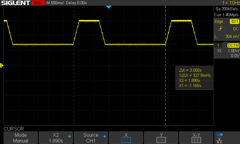
The first controller set up is a PIDF controller designed with pressure as input and non-dimensional control effort from [0-1] as output. Some common-sense practical features such as integral anti-windup, integral-acting error range, and error derivative filtering are implemented. As we do not yet have any sensors or a blower to actually control, for initial validation only the feedforward term is used, which effectively multiplies the desired pressure setting by a constant to generate the control effort. This is mapped to 3.3V on the DAC, and we can see on the oscilloscope that the desired trapezoidal profiles are generated.
In the case below, the system was set for 20 BPM, or 3s per breath with an IE of 3:1. The internal oscillator on the MCU is used, so timing isn't perfect, but very close.
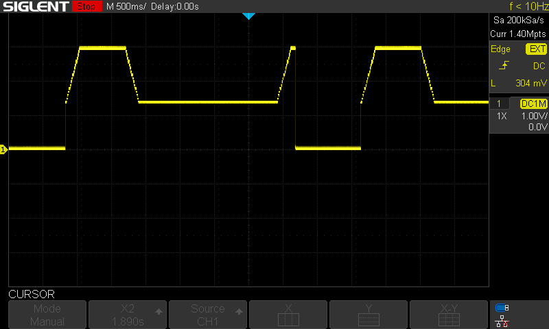
For safety, the system shuts off the motor if the enable switch is turned off. We need to be careful if the system is turned back on that there isn't retained memory of the pressure profile such that we jump straight to PIP level on re-enabling the system. The below image shows how the profile always restarts. In the future, we may add even softer ramp-up starts. Of course, the pressure increase won't be as sharp as the DAC output.
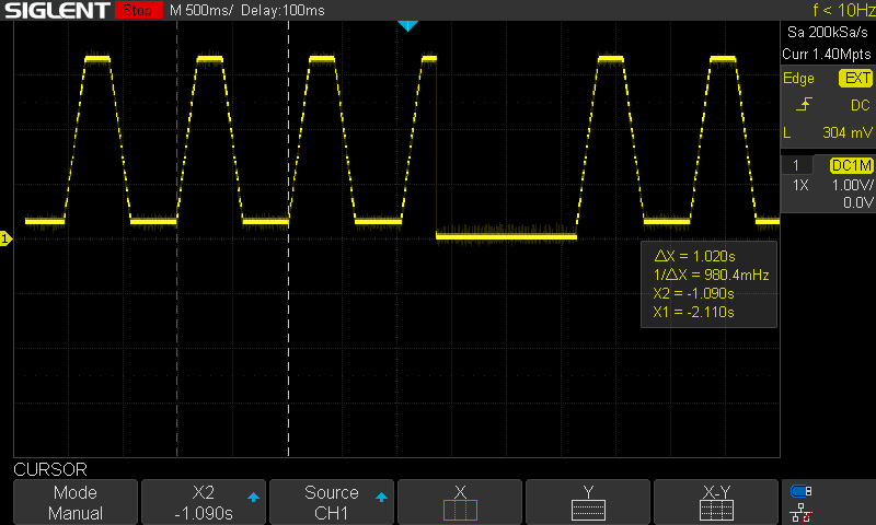
The case below shows the extremes we currently allow (although subject to future tuning), at 60BPM, maximum PIP, minimum PEEP. This case has IE of 2:1, although with the rise and fall times still at 200ms each, it is more difficult to see this. It also shows the system disabled at PIP, then re-enabled safely.
By using a professional development environment, and professional tools such as FreeRTOS, we bring more safety and reliability to this project.
Discussions
Become a Hackaday.io Member
Create an account to leave a comment. Already have an account? Log In.