A few weeks back, we made a bunch of orders for parts, including our assembled PCB. This week, the hardware finally arrived and we have been hard at work assembling and testing! So far, the focus has been on testing of the PCB, getting the firmware up and running on it, and addition of firmware features which were not easy to test on the breadboard version since that version did not have all of the necessary components.
For cost and timeline reasons, we had only the surface mount components assembled for us, and left the through hole components for us. The board was built by Macrofab, who I have used for many projects and highly recommend. Their boards have always been high-quality, their price is great, and their UI is really easy to use.
When it arrived, the board looked like the following:
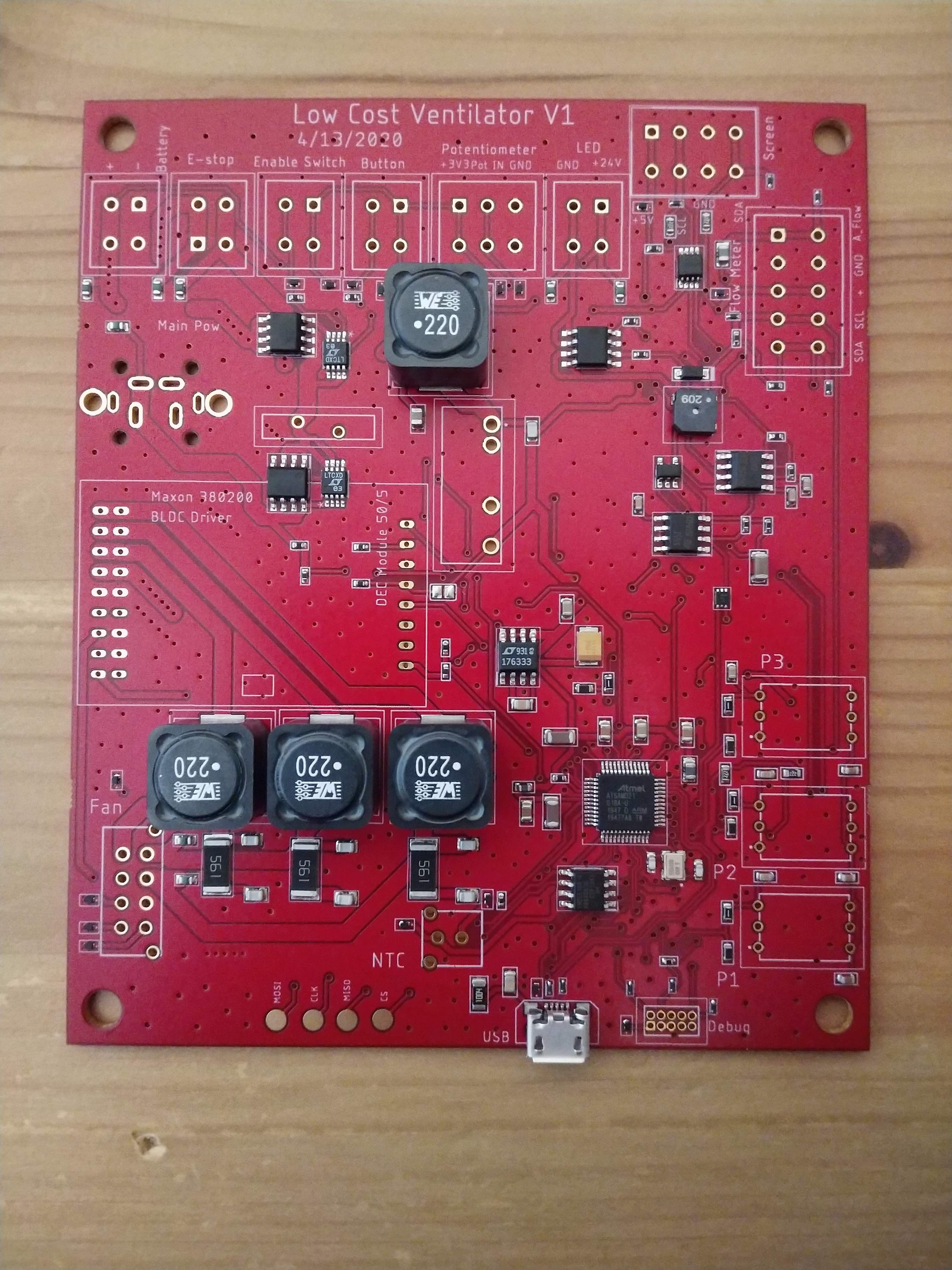
There is a lot to note here. First, one can see a lot of safety features that were built into the design. All of the connectors to external parts are ESD protected. Many of the other features of the design are also visible but will be discussed further later. Since the idea of this design is to be low-cost, that doesn't simply cover the cost of components. We also designed it in such a way that the PCB can be built in basically any fab for a low cost. We use generous minimum isolation and width for all traces (none smaller than 10mil, with most much larger than that). The design has all SMD parts on a single side, and it is only a two-layer board.
HARDWARE TESTING
I started assembling the board, going slowly to check all connections for polarity and for any mistakes we might have made in the design. Thankfully, there was nothing impeding the system from being powered up.
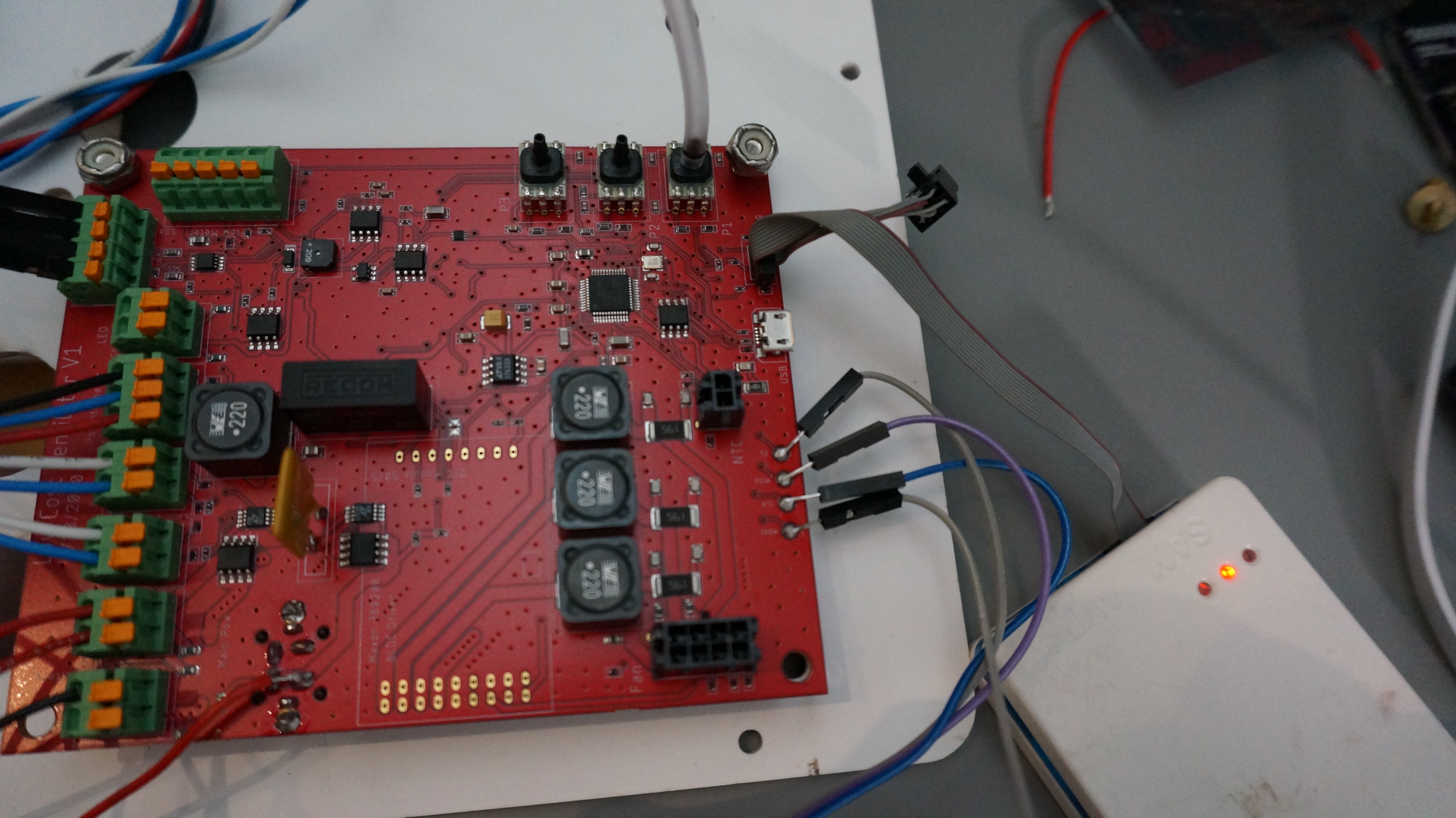
First, here is the board with the 5V regulator, spring pin connectors, programming pins, and motor NTC connector soldered in.
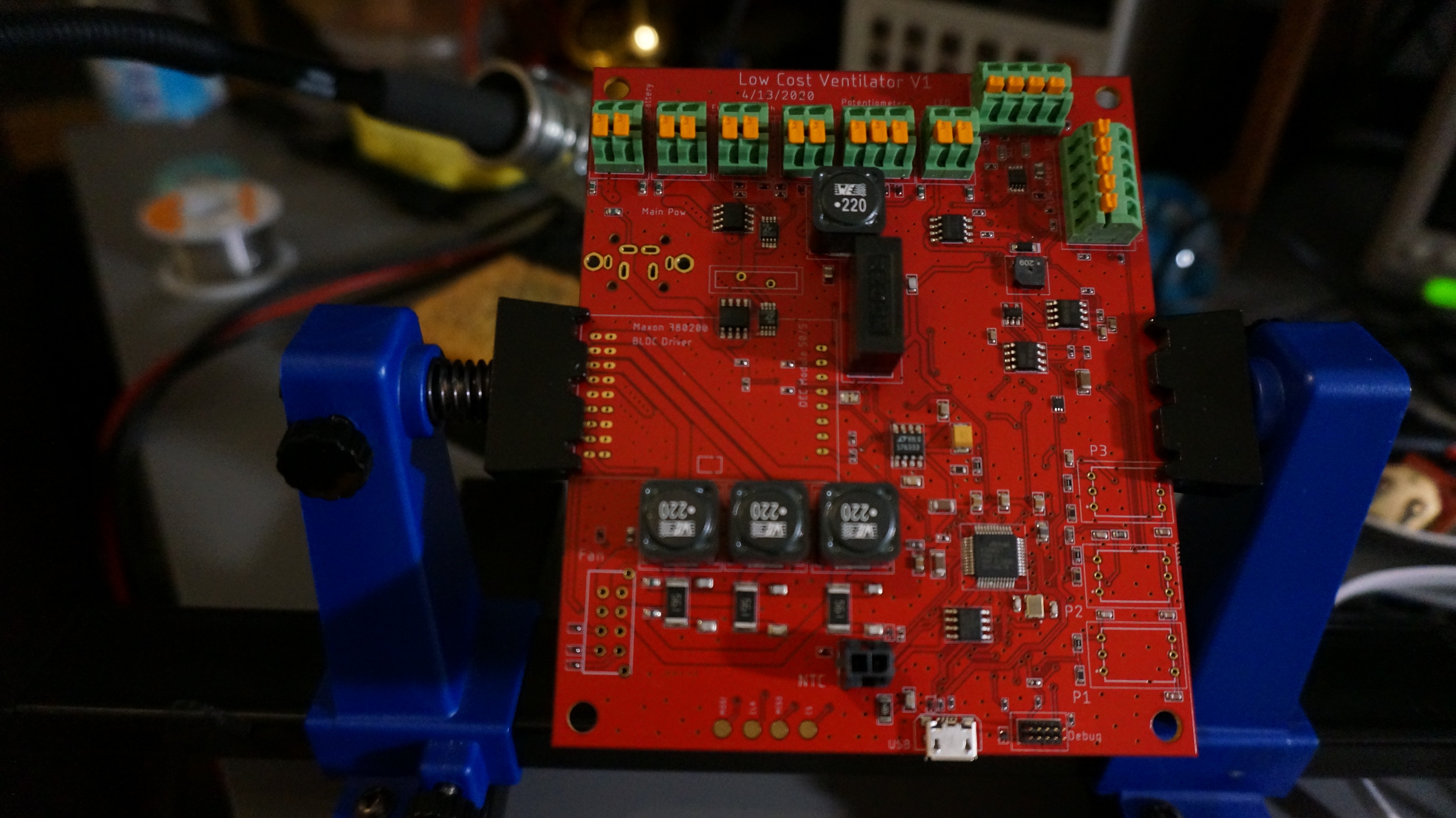
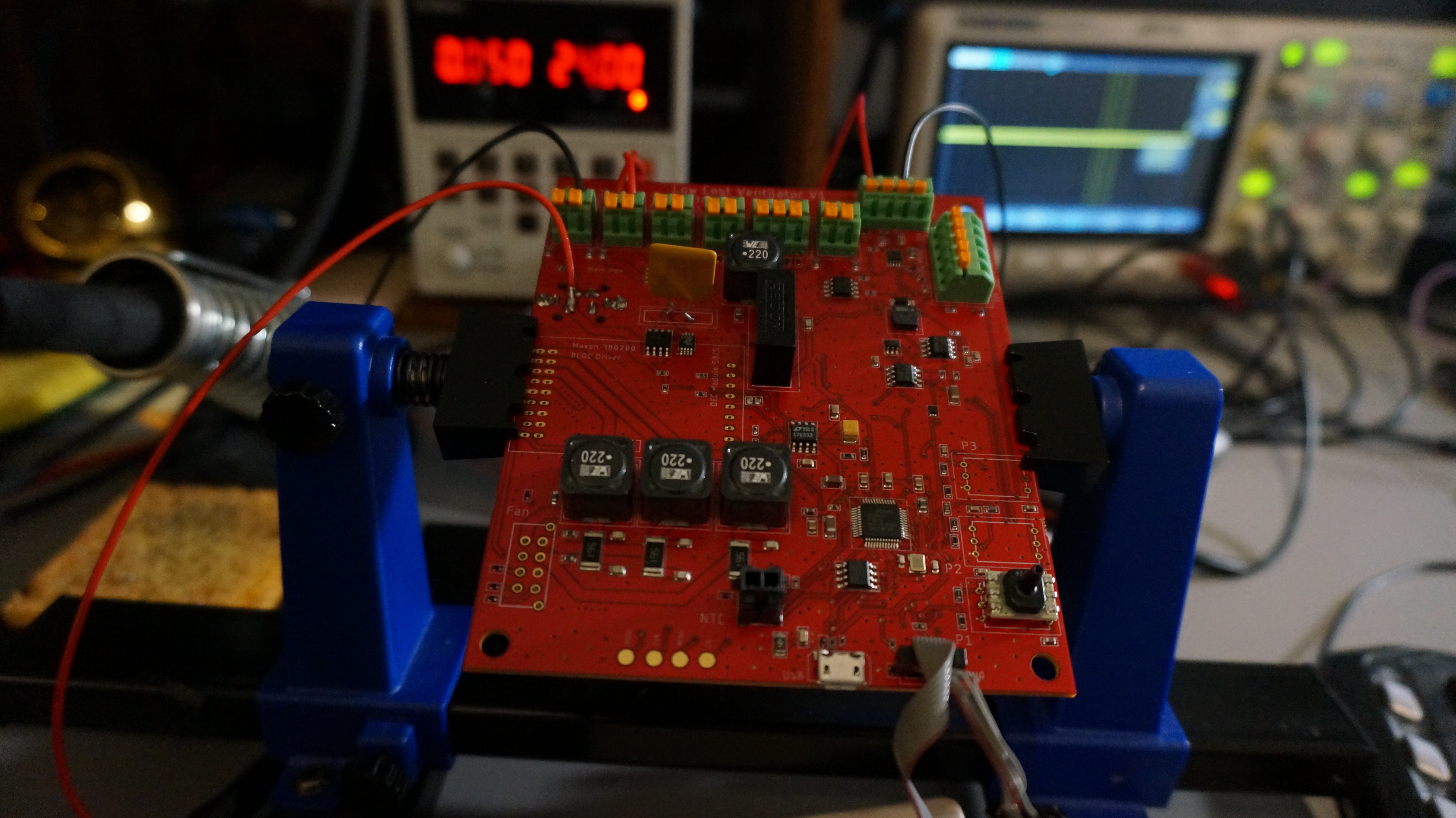
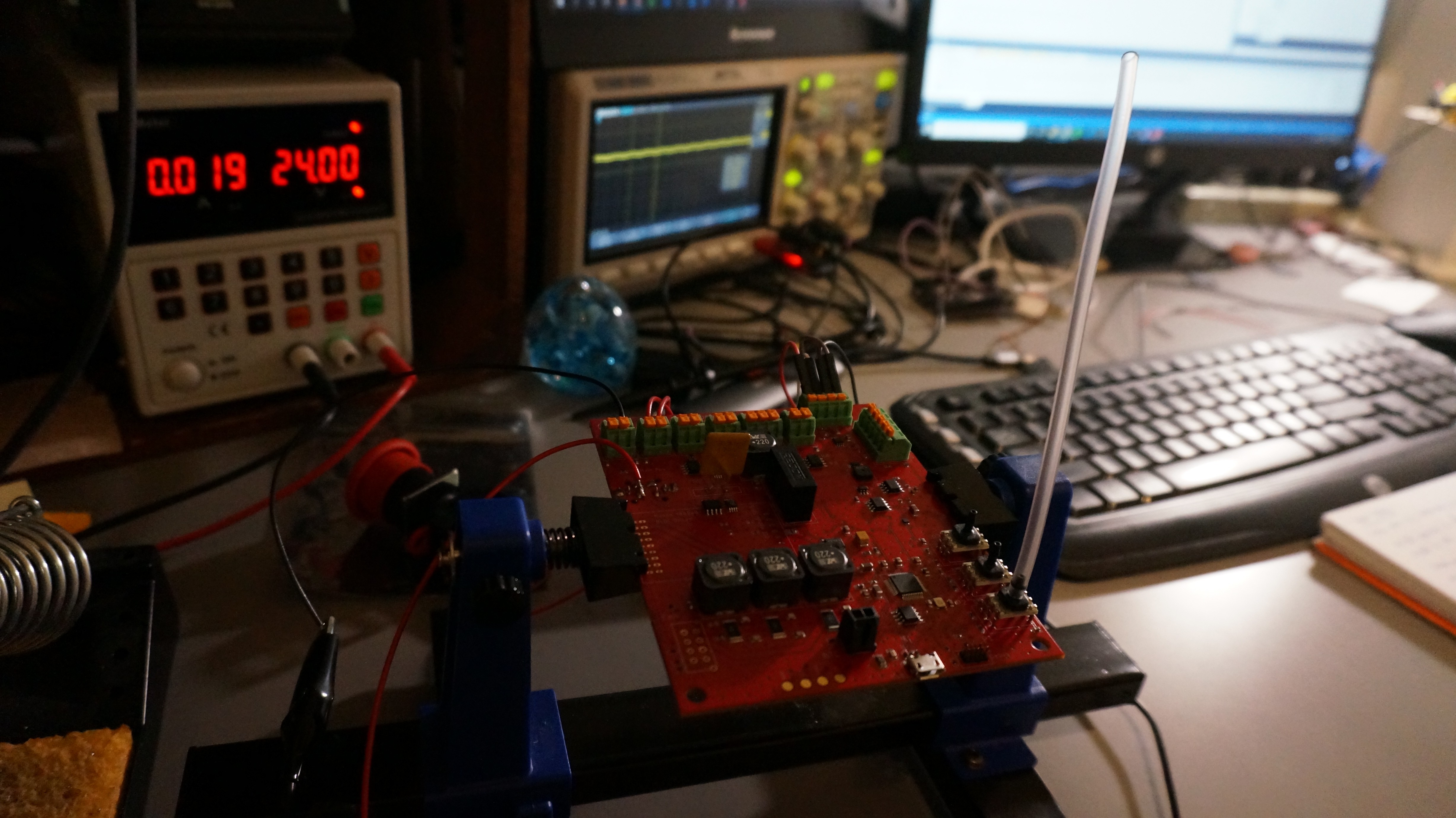
Here, one of the pressure sensors, the fuse, and the main power connector are also installed. The E-Stop switch is wired in, since the system cannot power up without it. The wires on the top right were connected into 5V and GND so I could examine the 5V rail with my oscilloscope (it looks very clean). The red wire soldered onto a pin near the top left of the board was added so that I could power the system from my power supply. Normally, the design uses a COTS medical-grade power supply, but for testing I wanted to be able to limit and monitor current. Thankfully, that wire can be removed once I am done testing - it is not a bodge wire.
Once I had confirmed that the single pressure sensor was functional and acting as expected, I mounted the other two. This design uses triple-redundant pressure sensors for reliability. Here, the LCD screen is also connected. Since the LCD interface was something I had previously prototyped with a development board, it worked perfectly the first try with no firmware changes needed.
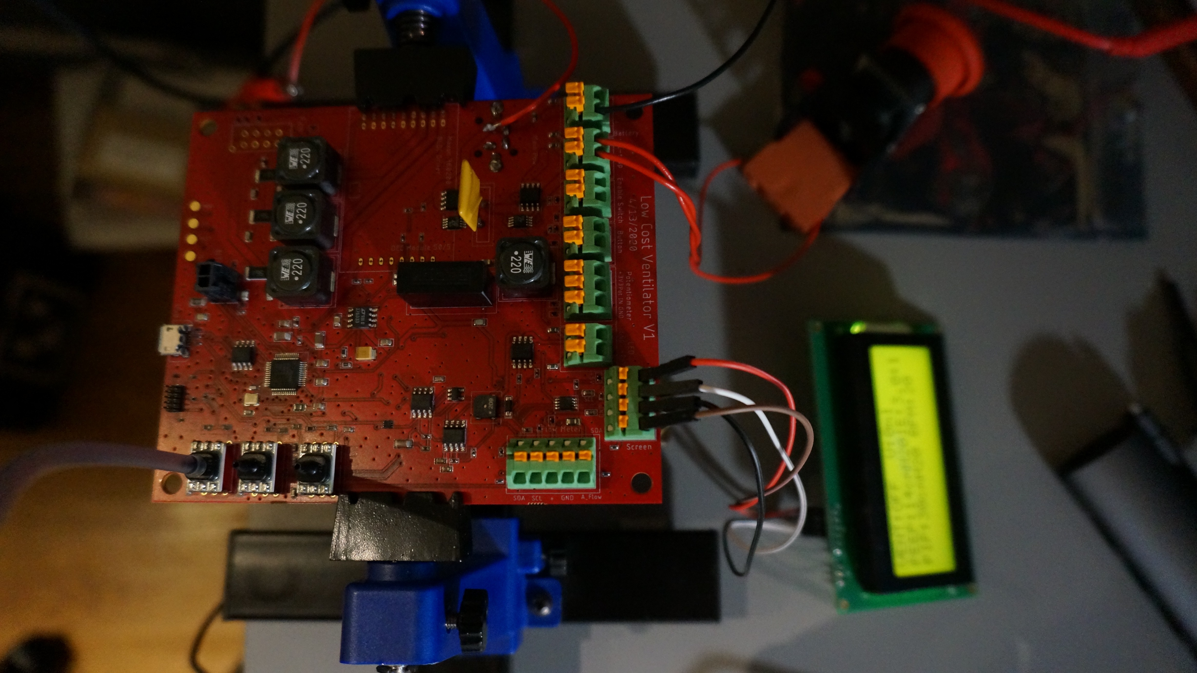
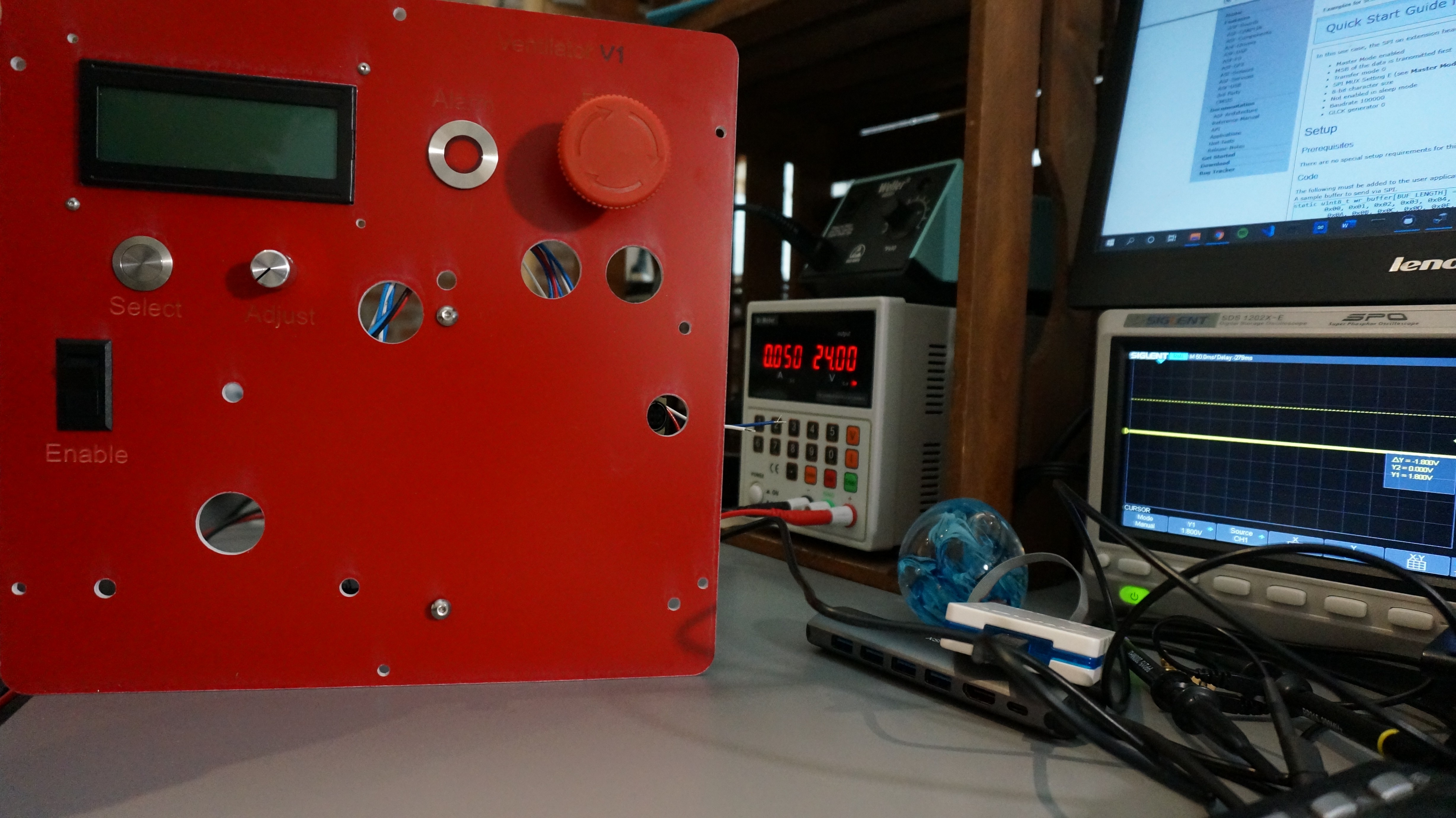
I hooked up a short tube to one of the pressure sensors to confirm that it was measuring pressure changes. It was. The nominal operational current is shown at 19mA at 24V, including the backlit LCD screen. The blower motor and its controller are not installed here.
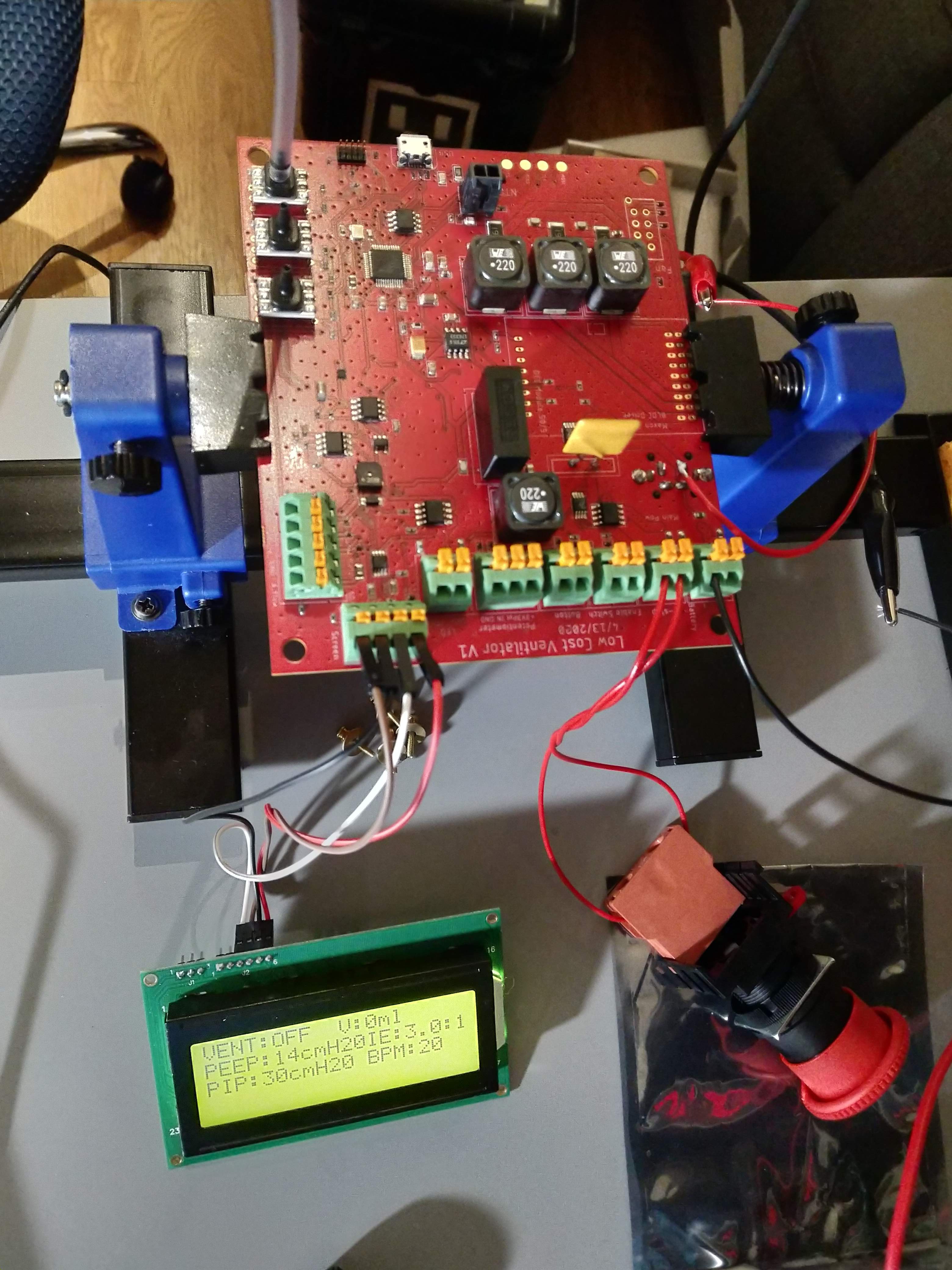
This image more clearly shows the preliminary display format for the ventilator. This is very much subject to change in the future, but is a useful start,
In order to simplify manufacturing, the LCV is designed around a COTS enclosure from Hammond. One of the front panels will be replaced by one of our own design. Therefore, the only main custom hardware element needed is a single "2D" part, easily produced on a laser cutter or waterjet. Our prototype panel is laser cut from acrylic, but acrylic should not be used for anything other than a prototype. Acrylic is damaged by alcohol, so it would be difficult to clean this system. The image below shows the PCBA roughly installed in its correct spot. The screws we bought were too short so it isn't fully installed yet, but the placement seems good. The enable toggle switch and the UI pushbutton and potentiometer are also installed and wired up. The alarm LED is installed on the panel between the LCD and the E-Stop switch, but not wired up. In testing, it seems to have a huge inrush current that we were not expecting, so we are choosing an alternative now.
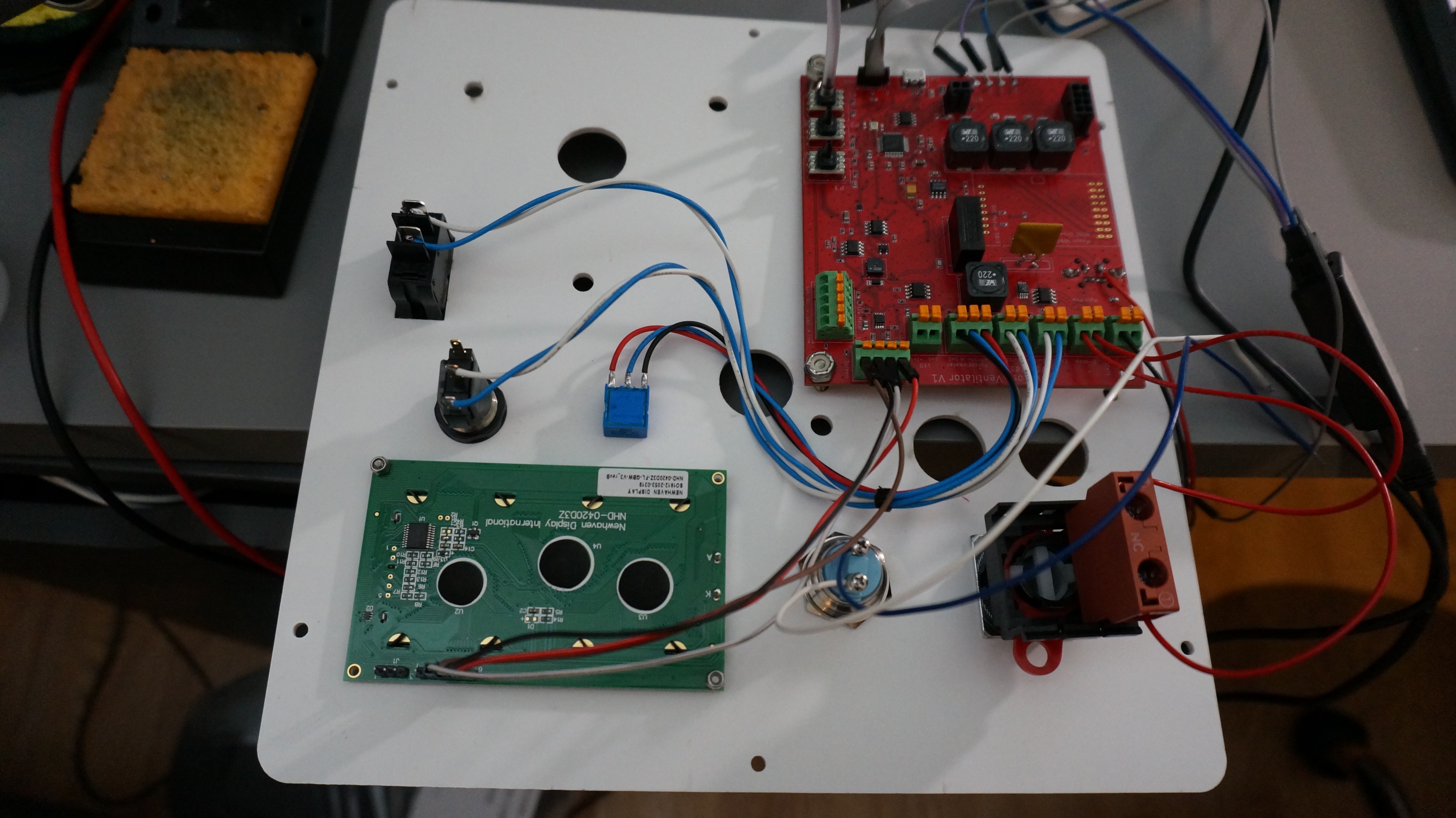
The image below shows the other side of the panel. The remaining holes in the panel are for the breathing circuit, which is not yet installed.
Overall, the hardware side of the project is progressing nicely!
FIRMWARE TESTING
Alongside the hardware build and testing, the firmware has also been under development. Because I had built a breadboard prototype with the correct MCU, LCD, and UI buttons and knobs, the main firmware was already ready to go. We are using FreeRTOS and the firmware is being written to use interrupts for peripheral interfacing wherever possible. The I2C interface to the LCD is done this way so that it cannot block and does not interfere with any other operation even though it is operated quite slowly (45kHz) and a lot of data is being sent (full 80 byte frame buffer at 30Hz + interfacing overhead).
There are a few main features that were not ready to go yet. The design has a separate hardware watchdog IC which must be "fed" by the microcontroller periodically. This is done by toggling a pin from the microcontroller to the watchdog. If this stops, the watchdog triggers the board mounted piezo buzzer and alarm LED to fire. In this way, if the microcontroller ever gets stuck, the operator will be notified. This is an important safety feature. When first powering on the system, I had forgot about the buzzer. The first power-up of any new design is scary, so when a loud buzzer immediately triggered, it startled me to say the least! Thankfully rather than an issue, this indicated the watchdog was operating as expected. Indeed, if I stop the MCU during debugging, the buzzer is triggered. While annoying for development, this is exactly what we designed it to do.
The other main feature not included in breadboard prototype is support for high-speed non-volatile storage. The microcontroller we are using is not one designed for safety critical systems. Nonetheless, we want to bring as much safety to the system as we can. One of the ways this is done is that the internal watchdog on the MCU is set to have a very short timeout. If the MCU locks for even a short time and the control loops is delayed, the MCU will be reset. However, when we do this, all operational state information and settings are lost. Therefore, the state information is periodically written onto fast, non-volatile FRAM storage during normal operation, and loaded on boot. Therefore the system can come back up in a known state and can continue operating safely. A CRC is used on the stored data to ensure its integrity. The FRAM we used is accessed through SPI, and can be operated at up to 20MHz. Unlike flash or EEPROM, it does not take extra time to write to it, it writes at the full bus speed. In addition, it has effectively infinite read and write cycles. Just like for the I2C interface to the LCD, the SPI interface here was written to be fully asynchronous and interrupt driven. It cannot block the operation of anything else. Therefore, we can periodically write to the storage during every control cycle and not worry about the overhead. Since we knew this would be a major firmware development that we couldn't easily prototype before, the board design included large test pads for all the SPI pins. The image below shows wires soldered to these pads that were then connected to a digital logic analyzer for debugging.
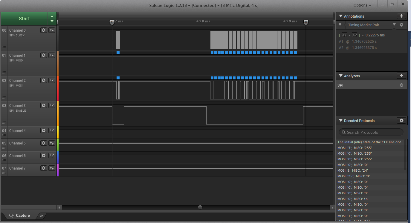
I am very thankful that we included these test pads. Debugging SPI can be very difficult without using a logic analyzer. In this case, it took some time, but I got it working. The image below is a screenshot of the logic analyzer data when a write occurs. The SPI bus is operated at 2MHz, and the entire write requires about 0.2ms. More optimization is certainly possible, but this is fine for now. This FRAM automatically locks itself from writes, so before any write a write enable command must be sent. That is what is seen here. The FRAM is unlocked and then the current settings are written to storage.
Operation Demo
A basic demo of the interface and operation of the system is shown in the video below:
NEXT STEPS
We are getting very close to hooking up the blower motor and the air circuit, and doing initial "breathing" tests! More to come.
Discussions
Become a Hackaday.io Member
Create an account to leave a comment. Already have an account? Log In.