 Ken Yap
Some months ago I came across an offer of 10 STC15F104W for about 30¢ each so I took the plunge. These are 1T 8051 MCUs with 4kB flash and 128B RAM. The only drawback is it is a DIP-8 or SOP-8 device so has only 6 I/O pins but this may be sufficient for small applications, and you can always extend the I/O with serial protocols.
The datasheet was easily found with a search and In System Programming only requires Tx/Rx pins, readily available from a USB to TTL converter. But being a lazy person I wondered if I could use my QX-mini51 development board since it already has the converter on board and I have already set up stcgal.
Looking at the pinout, besides the power pins, the 6 I/O pins are port 3.0 through 3.5 with P3.0 and P3.1 used for serial communications. I just needed an adaptor. I had some prototyping boards of the right size, so I soldered a DIP-8 socket and then wires to 8 pins taken from a broken precision (round pin) IC socket. I'm feeling chuffed about not throwing that away. I don't really need P3.2 to P3.5 but I wired them anyway. I soldered another pin at 21 for better registration. Here's the result:
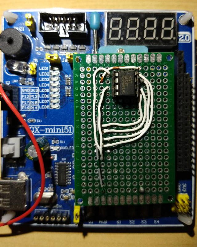
BTW the datasheet suggests isolation diode and resistor to prevent powering the MCU from the USB serial adaptor. This is not necessary since there is only one power supply, that feeding the QX-mini51.
I connected up the board to the USB port, ran stcgal, pressed the power switch and got this:
$ stcgal
Waiting for MCU, please cycle power: done
Protocol detected: stc15
Target model:
  Name: STC15F104W
  Magic: F294
  Code flash: 4.0 KB
  EEPROM flash: 1.0 KB
Target frequency: 0.000 MHz
Target BSL version: 7.2.5Q
Target wakeup frequency: 35.650 KHz
Target options:
  reset_pin_enabled=False
  clock_source=internal
  clock_gain=high
  watchdog_por_enabled=False
  watchdog_stop_idle=True
  watchdog_prescale=64
  low_voltage_reset=False
  low_voltage_threshold=3
  eeprom_lvd_inhibit=False
  eeprom_erase_enabled=True
  bsl_pindetect_enabled=False
  por_reset_delay=long
  rstout_por_state=high
  uart2_passthrough=False
  uart2_pin_mode=normal
  cpu_core_voltage=unknown
Disconnected!
If you're wondering why the target frequency is 0, this MCU family has an onboard oscillator.
Update after 2½ years
I finally got around to writing firmware for a project using these tiny form factor MCUs which I will post about in due course. However when I tried to flash the firmware on the MCU, I ran into some glitches which I am pleased to say I solved.
- A silly error on my part. I couldn't connect with the QX board until I realised that because I had an Arduino Uno plugged in, the QX board was allocated /dev/ttyUSB1 instead of the /dev/ttyUSB0 I wrote in my Makefile.
- I got my workstation talking to the MCU, but got this error message.
Protocol error: uncalibrated, please provide a trim valueA search took me to this issue in the stcgal project: https://github.com/grigorig/stcgal/issues/96 Simply put I have to provide an operating frequency for the MCU. This also answered my question about what frequency the timers would run at, which is important for timing in the firmware. I chose a trim frequency of 11059 (kHz) as it will match that of the STC89C52 normally on the QX. Although the STC15W goes to 35 MHz, speed is not important.
Next I encountered this error message:
Protocol error: incorrect frame startThis took me to this issue: https://github.com/grigorig/stcgal/issues/17 It's quite a long thread but to cut to the chase, I needed to update my stcgal version, which simply required:
git pull
./setup.py build
sudo ./setup.py install
It still wouldn't program at the default 115200 baud, but when I dropped to 38400 baud, it worked fine.
Discussions
Become a Hackaday.io Member
Create an account to leave a comment. Already have an account? Log In.