The goal of this task is to describe the steps needed to translate a neural network onto a discrete component implementation
Sample neural network
As a starting point we'll use a simple neural network with two inputs or signals and two outputs or classes. In the MNIST example, each input would be a sensor on the 4x4 matrix and the outputs or classes would be digits from 0-9.
In the image below we have a neural network composed of two neurons, identified as 0 and 1. Since this neural network has no hidden layers, the output neurons are the only neurons.
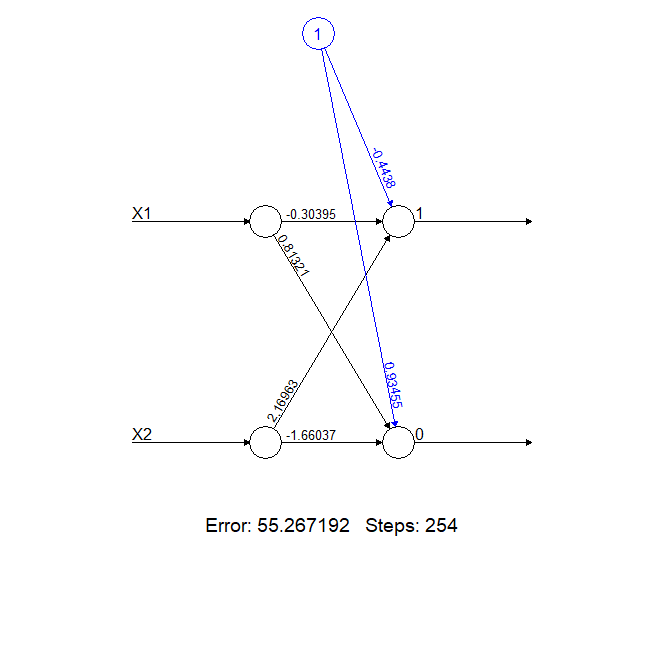
The calculations carried out at the neurons are as follows:
- Neuron 1 = Bias (-0.4438) + Input X1 * weight_X1_1 (-0.30395) + Input X2 * weight_X2_1 (2.16963)
- Neuron 0 = Bias (0.93455) + Input X1 * weight_X1_2 (0.81321) + Input X2 * weight_X2_2 (-1.66037)
We'll now translate this onto a memristor as follows:
- Each neuron's (0 or 1) signal will be calculated as a summation of currents
- The bias term will be translated onto a current (positive or negative).
- The Input * weight terms will be translated onto currents (positive or negative).
- All the terms will be channeled onto a wire and the summation current will be transformed onto a voltage signal using a resistor. The signal will vary in intensity with the increasing current across the neuron.
Positive value currents will be simply calculated as the product of the incoming voltage and conductance of a resistor (I = V x G or I = V / R). The resistor has to be chosen so that the conductance of the resistor equals the value of the weight. For example, in the neural network above, for Sensor X1 and the Output signal 0, the weight equals 0.81321 and the equivalent resistor would have a resistance of 1.2 ohms. The resulting current will be injected into the neuron wire.
Negative value currents will be calculated by multiplying the incoming voltage by a suitable resistor. The resulting negative current will be subtracted (removed) from the neuron line using a transistor. The resistor has to be chosen so that the conductance of the resistor equals the weight divided by the beta of the transistor. For example, in the neural network above, for sensor X1 and the output signal 1, the weight equals -0.30395. Assuming the transistor has a beta of 100, the resistor would have to be (0.30395/100)^-1 = ~300 ohms. There is a better way to do this and this was suggested by the vibrant community in the .Stack in order to avoid the impact of beta variation as a function of Collector current. We'll stick to this simpler solution for now and discuss the alternative implementation below.
Finally, the bias in neuron 1 is a negative one. Hence we need to use the transistor to subtract current from the neuron line. The value for the bias is -0.4438. Using the same procedure as above, we'll calculate the resistor value as (0.4438/100)^-1 = 225 ohms.
Adding it all up
In order to add the currents and get the output of the neuron, we use a wire joining all the currents and display the signal as intensity of a led. We could also measure the voltage with an ADC if we wanted to handle the output digitally.
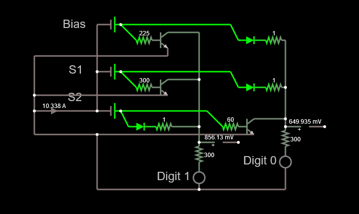
The resulting circuit is simple, if slightly dangerous if we pay close attention to the ammeter below the S2 signal. The reason for this is the amount of sensors. Since the number of sensors is small and the data poor, we are stuck with very large weights and biases. This means that if we move the sliders controlling the voltage from the sensors to their maximum values, we get currents in the order of a few amperes. When scaling up to as little as 16 pixels/sensors, this is not the case anymore and the weights and biases are much smaller. We'll tackle this issue later.
An improved negative weight calculation
Since the beta of the transistors is not a reliable number, I asked the .Stack to lend a hand to try to solve the issue caused by its variation. I got a lot of useful information. One answer led me to log this log, but all of them sent me on a way to solve the issues caused by the variability of beta.
Darrin B suggested using a current mirror instead of single transistor and that helped me to solve the beta issue. The updated circuit can be seen below.
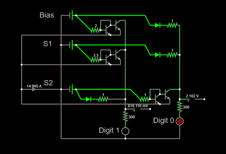
So, now the issue with the beta is solved, but we still have a 14.9 A current to deal with.
Since we're looking at the comparative signals between 0 and 1, we can in principle massage the maths as follows and still maintain the ratio between the two signals:
- Neuron 1 = Bias (-0.4438) / 100 + Input X1 * weight_X1_1 (-0.30395) / 100 + Input X2 * weight_X2_1 (2.16963) / 100
- Neuron 0 = Bias (0.93455) / 100 + Input X1 * weight_X1_2 (0.81321) / 100 + Input X2 * weight_X2_2 (-1.66037) * 100
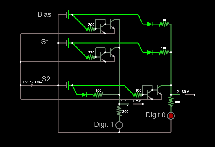
We then end up with the circuit below, which has a much higher impedance and a more palatable current.
Conclusion
Hopefully this task helps understand the basics of translating a trained neural network onto a discrete component affair.
There were some issues with the previous circuit design which have been solved with the feedback from the .Stack and some basic math.
The circuit for the MNIST number recognition neural network will be updated using the lessons learned and fingers crossed we'll have a prototype soon.
Discussions
Become a Hackaday.io Member
Create an account to leave a comment. Already have an account? Log In.