 Dillon Nichols
Hardware
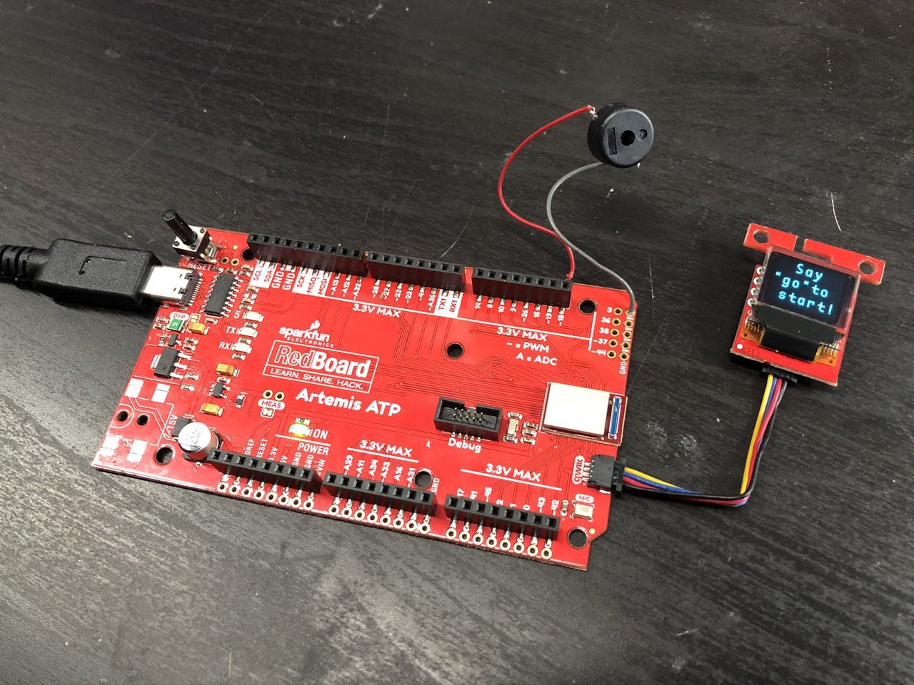
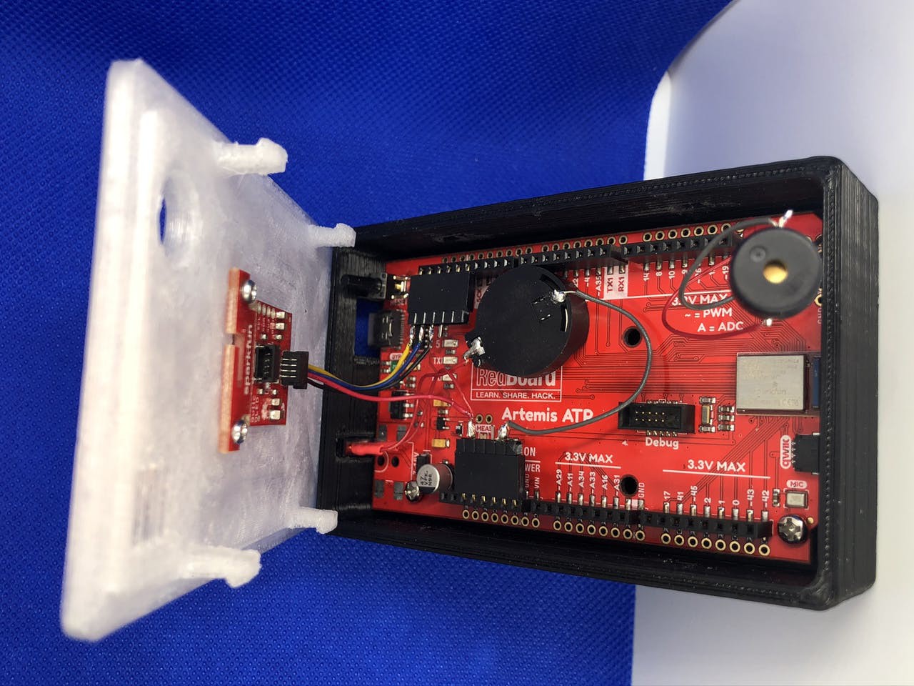
The two required pieces of hardware required for this project are a SparkFun RedBoard Artemis ATP board and a SparkFun Micro OLED Breakout (Qwiic). I've added a few more items and modified the board to improve the experience, but the whole project could be recreated without even using a soldering iron. SparkFun's Qwiic Connect System makes it really easy to work with these items. Just connect the items with the premade cable and everything will work.
I added a buzzer which produces a unique tone for each of the four directions. This isn't necessary, but it does provide a slightly more polished experience. An idea that I didn't get the chance to implement is to add LEDs that also relate to the four directions (I recommend a red, yellow, blue, and green LED to mimic the original design). An enclosure printed in transparent filament would work well to diffuse the LEDs. The software could also be extended to play tones or make light patterns in response to different states like the startup screen or the game over screen.
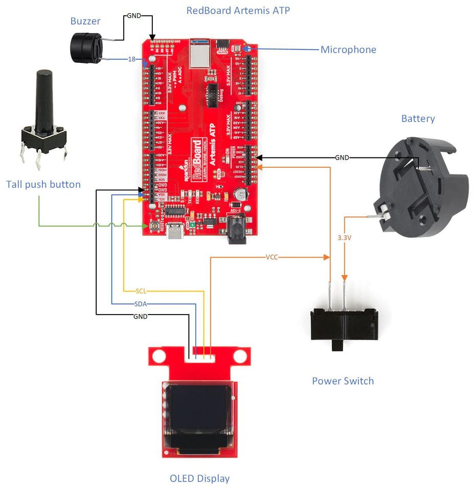
I had to make few modifications to the board due to my enclosure design (which will be discussed in the next section). The biggest change that I made is the removal of the power jack to make room for a power switch. The game draws about 9 mA while running and goes into a low power mode after quitting which drops the power usage to about 6 mA. This is higher than I expected so I think I could make some more optimizations to drop it even further. I added a different type of button to the board to extend the reset button outside the enclosure, which takes the board out of low power mode and starts another game. I used a different type of battery holder because I didn't want to mount the battery to the back of the board and make the enclosure larger. I added a hard power switch inline with the battery for when the game isn't going to be used for an extended amount of time. My enclosure didn't leave room to use the Qwiic connector on the board, so I rewired the cable directly to the pins instead.
Enclosure
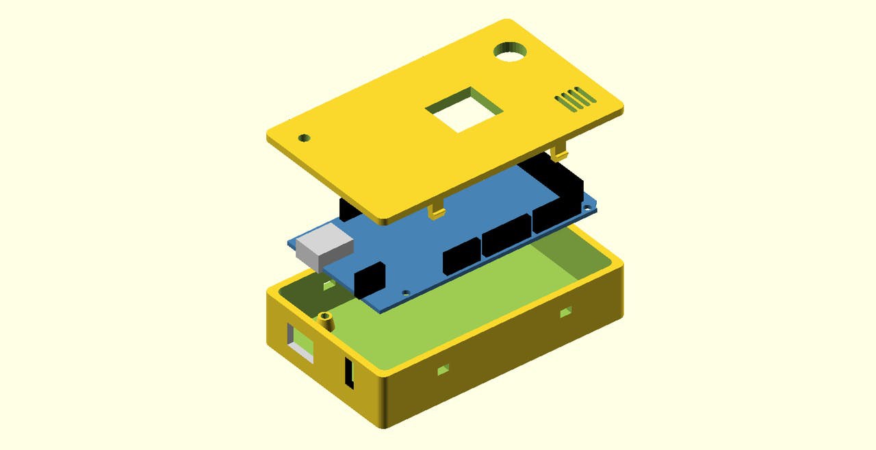
My enclosure is based on the Arduino OpenSCAD mounting library (v2.0). I really enjoy using OpenSCAD to design simple enclosures, so I was thrilled when I found this library. After printing out my first revision of the enclosure, I realized the RedBoard Artemis ATP is not the standard size for an Arduino Mega so I had to hack up the library to make it fit. I spent a lot of time trying to do it the right way, but then I realized it wouldn't really give me the result I needed.
A major design constraint is the limited size of my 3D printer bed. My longest axis is 112 mm wide and I managed to squeeze the enclosure into 111.6 mm. This is the reason that I needed to rewire the display -- I just didn't have room to extend the enclosure so that I could use the Qwiic connector.
The mounting holes on the board lined up, so I just had to make the enclosure wider for the wider board. I modified the USB hole to go from a Type B to a Type C with room for the cable I have. I modified the power jack's hole so that it fits the power switch snugly.
The lid was also modified to make it as wide as the enclosure. Besides that, I added holes for the reset button, buzzer, display, and microphone. The display is mounted with screws to the bottom of the lid. I made a speaker grill design so that the microphone can still hear me.
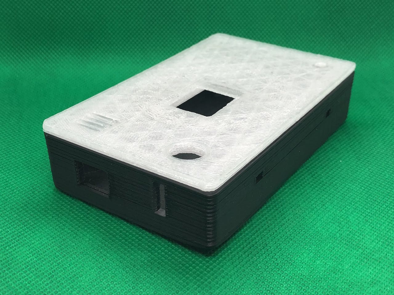
You can find my source files for the enclosure on my GitHub (specifically enclosure.scad) or Thingiverse (includes some extra photos).
Software
There are two different development methods for the Artemis module: Arduino or the Ambiq Apollo3 SDK. I thought the Ambiq SDK was required to use Tensorflow, but after having a lot of trouble setting it up, I found a project that uses Arduino and Tensorflow. My project is based on the ArtemisATPTensorflowMicroSpeech project and I don't think I would've completed my project without this baseline code. This code sets up the microphone on the Artemis ATP and explained how to use Tensorflow with Arduino.
The Software Setup document is a perfect explanation on how to set up the development environment, so I won't bother repeating it here. It does say it in the instructions, but ensure you install the non-precompiled version of the TensorFlowLite library, or you'll have baffling build errors.
Here is my source code for Arduino is located on my GitHub (specifically ArtemisSays.ino).
I used various libraries to add functionality to that baseline code. The SparkFun Micro OLED Breakout Arduino Library was used to write text and draw images to the display. I designed the images in Inkscape and converted them to code using LCD Assistant. Those files are in the display-images directory. The Tone() function was used to play notes on the buzzer.
I also retrained the machine leaning model using Tensorflow in Google Colaboratory. It's all explained in this document. The only thing I had to change was the list of words I wanted to use and wait an hour or two for it to spit out the data to put in my code. These are the words I chose:
os.environ["WANTED_WORDS"] = "go,right,left,down,up,no,yes"
After testing the new model, I had to change a few parameters in my code so that it reacts quicker and is more sensitive to words. These parameters work for me, but can be changed if the code doesn't recognize your voice accurately.
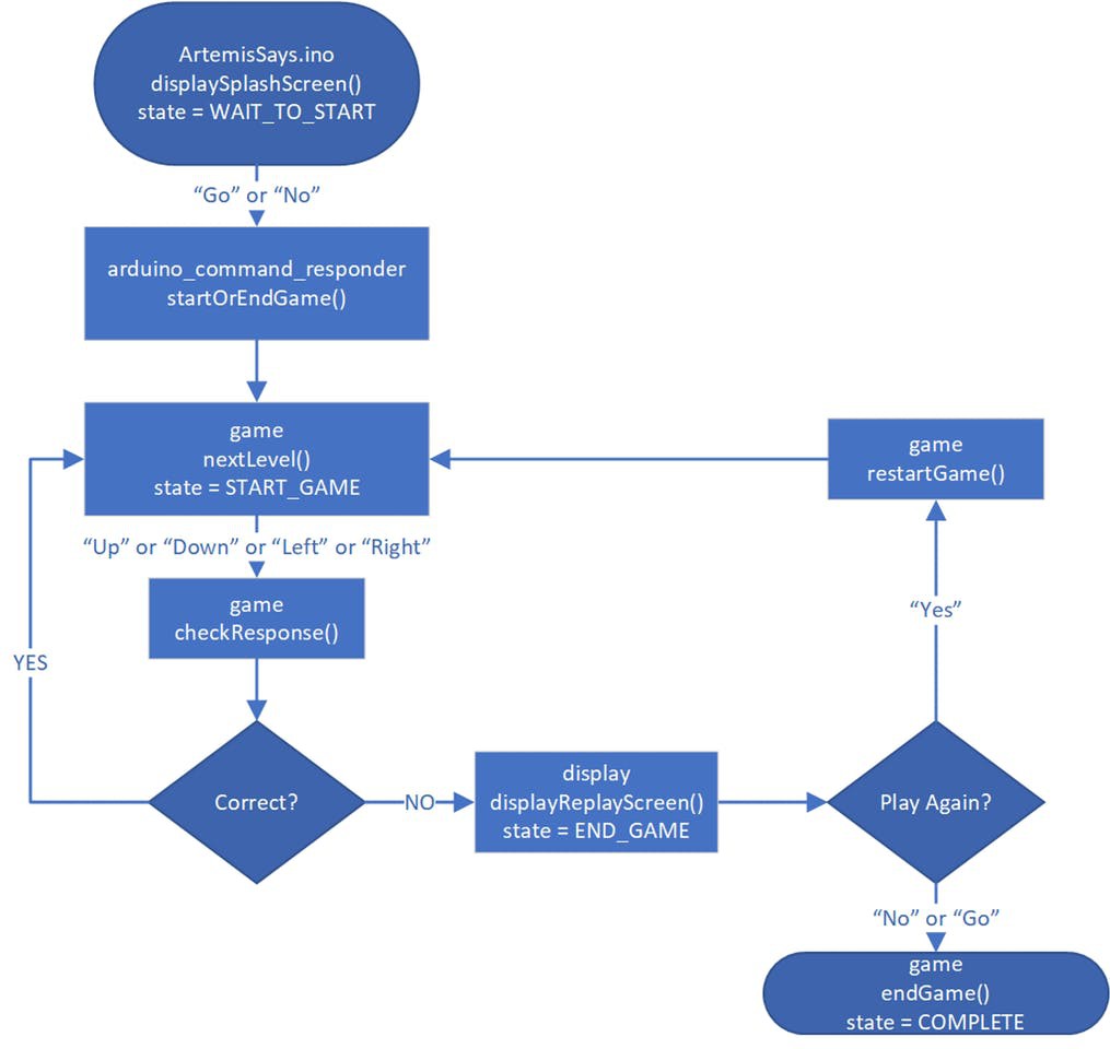
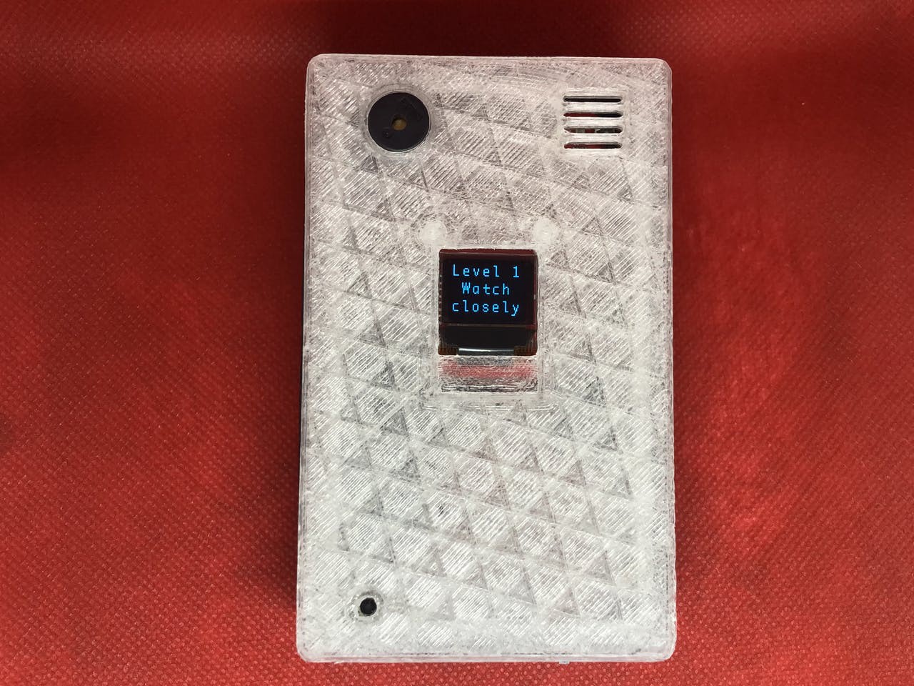
Now that I have all of the code to interact with the real world, I had to design the game. The above image is the state machine for the code. It starts by displaying a splash screen with the project name and some starting text. Saying "Go" or "No" starts the game. Ideally it would only respond to "go" to start, but occasionally, it thinks it hears "no", so I let either of them work. The same thing happens at the end of the game. It's a Yes/No question, so I made "No" or "Go" work the same. This decision is made inside startOrEndGame() and the state of the game decides the next step.
nextLevel() moves from one level to the next. It's used to start the game (move from level 0 to level 1) and to increase the level after a round is won. This function uses random() to pick a random direction and then displays the full sequence on the screen. Next, the game starts listening to the player's voice.
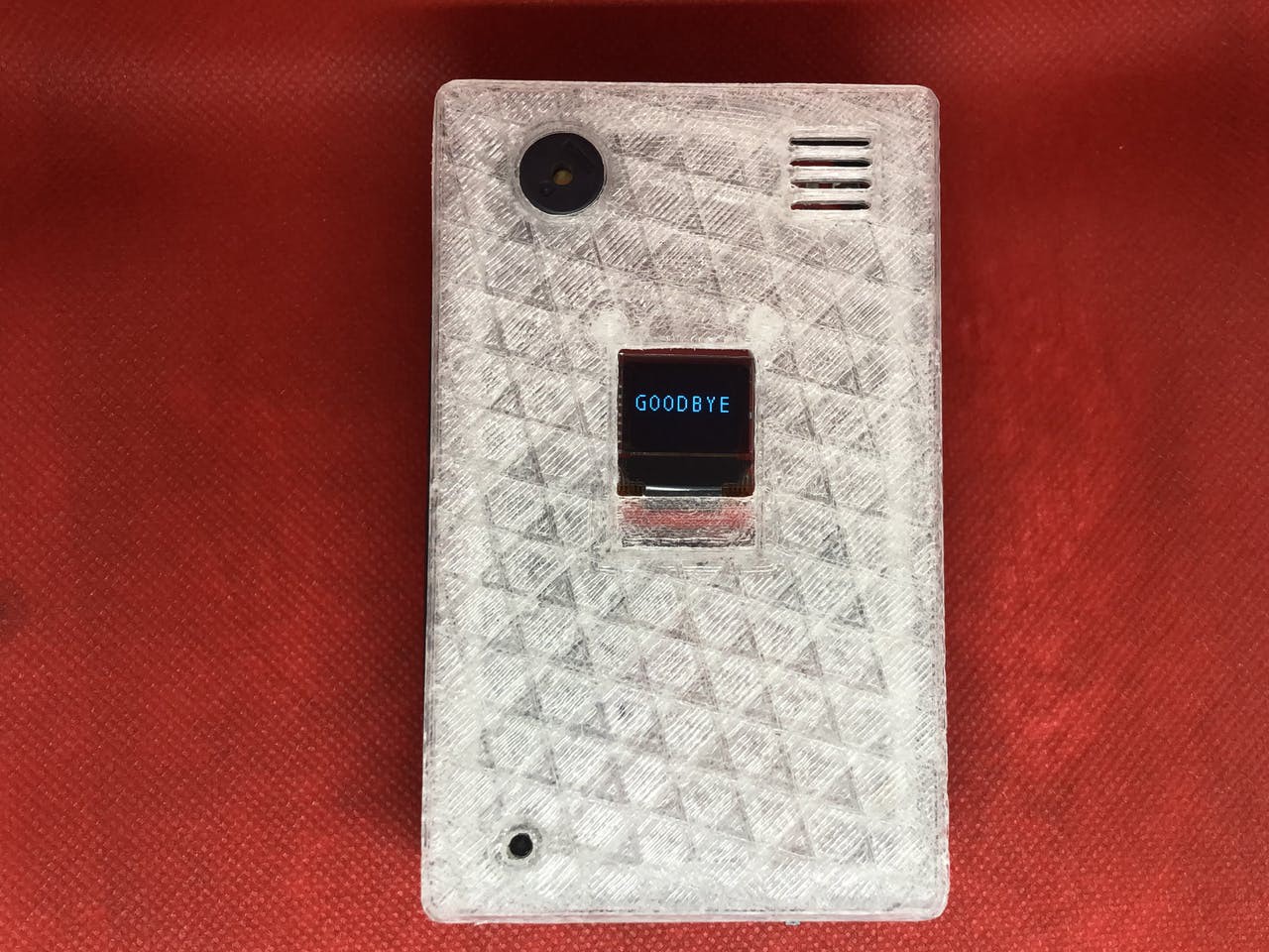
checkResponse() takes the direction spoken ("up", "down", "left", or "right) and displays that direction. If it's the correct direction, it lets the player say the next direction until they are all said. After that, it moves to the next level. If the direction is incorrect, some text is displayed using displayReplayScreen() to ask the player if they want to replay. An answer of "yes" starts the game. "No" (or "go" as described earlier) displays a final message using endGame() and then the device is put into a low power state that can only be woken up by pressing the reset button.
The code also spits out debug messages over serial at 9600 baud if you want to see what is going on behind the scenes.
Conclusion
This project would not have been possible without the great contributions of open source code, hardware, and documentation. I'd like to thank Sparkfun for the cool hardware, javagoza for the code to get me started using Tensorflow on Arduino, and Tensorflow for making machine learning accessible. I've never implemented machine learning in a project before and their documentation made it pretty painless. I'm still amazed that a microcontroller powered by a coin cell battery can listen to voice using a microphone and understand the spoken word. This really opens up a new level of interactions with low power devices.