This is more of a "dump" than a log.
I took apart the display and traced out the LCD PCB using a combination of a multi-meter, and by taking photos of both sides of the PCB and overlaying them in Photoshop.
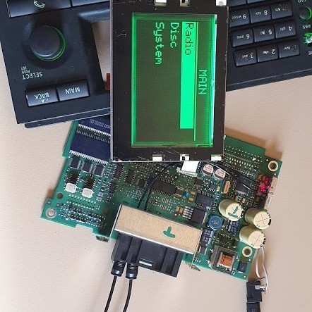
I then had to convince the ICM2 unit to turn on the display for me, in order for me to measure voltages and data being sent to it. I knew that I had to complete the MOST ring-bus loop before the ICM2 would boot, so I did that by shoving a plastic S/PDIF cable into the MOST port:

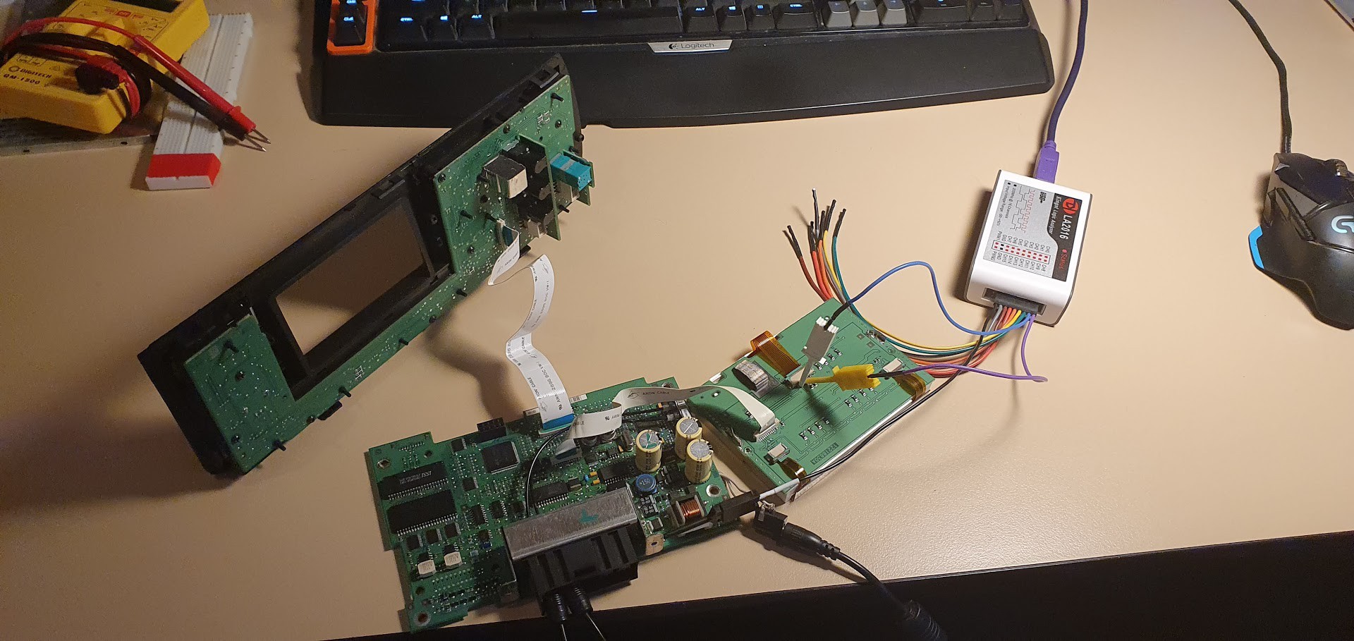
That worked perfectly! I was then able to plug in my Kingst LA2016 logic analyser...

...and by doing so I could identify that an I2C bus was being used to control the display.
I then made a full schematic of the PCB circuit using KiCAD 5 - mainly to practice drawing schematics - and also to have a place to store important electrical notes regarding the display interface.
I don't have any good-quality photos, but I actually reverse-engineered the I2C commands by using a BusPirate V3 (python scripts used are in the GitHub repo). I then moved onto using an ESP8266-based NodeMCU board.
I initially translated the BusPirate python scripts line-by-line into C for the Arduino, before creating a proper library for the display by inheriting from the Adafruit_GFX class. (Note: it is very roughly made...)
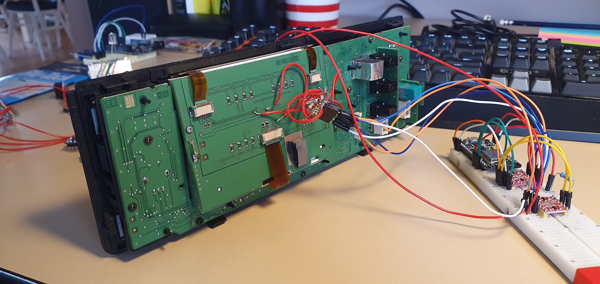
Here's what the wiring for that looked like - with wires soldered onto vias on the back of the LCD module and plugged straight into a breadboard:

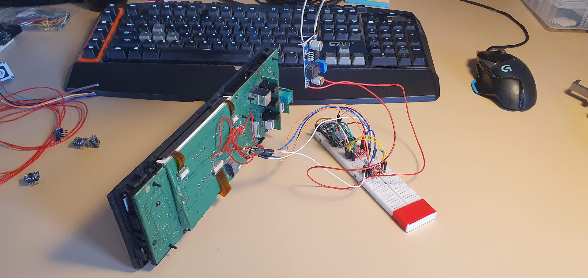
My current hardware setup looked somewhat like this, with an included DC-DC step-down converter. The step-down converter is usually set to output around 7V - this is because the LED back-light array(s) need about that much (plus pulse width modulation for brightness control) in order to achieve better brightness:

That's all for now - I'm waiting on some parts in the mail to "break out" the 0.5mm FPC connector into a through-hole format. Hopefully this will allow for a less invasive install procedure (by plugging directly into the intended ribbon cable) - and will result in less issues with dodgy wire connections.
I do wish to experiment with an I2C multiplexer - to allow for in-system switching between "stock" and "custom" display routines. Endless possibilities, endless fun!
 Leigh Oliver
Discussions
Become a Hackaday.io Member
Create an account to leave a comment. Already have an account? Log In.
You could hook up the multiplexer to the extra button on the dash. It's a button with a line on it located right below the nightmode button. According to the SAAB forums the button was left unused by SAAB so people could install custom lights and toggle them. In this case you could use it to toggle the multiplexer perhaps?
P.S
I'm very curious about your project and I would love to have a go at it myself. Please check my other comment on "Adventures in drag-soldering, and groovin' on the ICM2".
Are you sure? yes | no