 Lars
LarsToday I want to continue with the basic system of the robot.
The article is structured as follows:
- Basics
- The Sensor
- Communication and behavior
Basics
Ultrasonic sensors can be used for distance measurements. They can detect objects without touching them and then output the distance from the object to the sensor. Therefore, the ultrasonic sensor generates a high-frequency sound wave of approximately 40 kHz. Ultrasonic waves spread out at an approximate speed of 343 m/s, which is roughly the speed of sound. Another characteristic of a sound wave is, that it is reflected after a collision with an object. This creates an echo that can be detected by the sensor.
The distance to the object can now be calculated from the time between sending and receiving the frequency.
s = (v*t)/2
s = distance in m
v = velocity in m/s = Speed of sound(343,2m/s)
t = time in s
The sensor
In the robot two HC-05 ultrasonic sensors are used. This sensor is characterized by a distance range from 2cm to 400 cm. The measurement result has a maximum deviation of +-3mm. A complete measuring interval has a duration of 20ms. This results in a maximum rate of 50 measurements per second. In addition, the sensor is also specified by a current consumption of about 15mA in normal operation.
Based on these characteristics, it can be said that the module is suitable for applications in a robot.

Communication and behavior
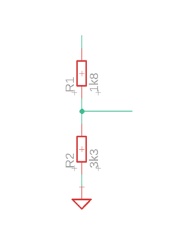
The module has four connections. The 5V supply voltage is connected to VCC and GND. Because the sensor works with 5V levels, but the FPGA only tolerates a maximum input voltage of 3.3V, the "trigger" and "echo" signals are connected to the FPGA via a voltage divider.
At the beginning of the measurement, the trigger signal of the sensor must assume the high state for at least 10µS. This starts the measurement and the module sends a 40 kHz burst signal for 200µs. Then the output signal goes to a high level and the sensor waits to receive the echo. If this condition occurs the output falls back to a low level. If no echo comes back, the output remains at the high level for another 200ms, symbolizing a failed measurement.
The following timing diagram illustrates the measurement process just mentioned:
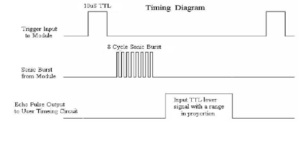
To calculate the distance to the obstacle, the behavior of the sensor must be evaluated from the FPGA. For this requisition, a counter is used to count the duration of the high level from the output signal. This provides a value for the time period, which includes the time from sending to receiving the ultrasonic wave. Accordingly, you must divide the value by 2 to get a time for the distance from the sensor to the object. Since the speed of the sound wave is constant, we now have enough information to calculate the distance s.
Discussions
Become a Hackaday.io Member
Create an account to leave a comment. Already have an account? Log In.