Digging into the documentation I started to get an idea of the complexity of the design, there's no way around this being a 4-layer design. Along with the dozens of passives and feed-lines required for the RF bits, power and signal lines would have to be routed in amongst it all to control the LoRaWAN RF path switch and LNA for the GPS antenna.
With size being important I started with an outline of the absolute maximum acceptable size and worked within its boundaries to fit everything in. 28mm x 18mm was my starting point.
All the passive components are 0402's, with a handful of 0201's scattered in there where required. I was planning on hand assembling the first test units, but that might be more hassle than it's worth at this point.
To keep everything tightly packed while maintaining good transmission lines for the RF I had to reduce my standard via hole size from 0.3mm to 0.2mm. This shouldn't cause too much of an issue since 4-layer impedance controlled PCBs are usually made with tighter tolerances and better capabilities than standard cheap 2-layer PCBs anyway.
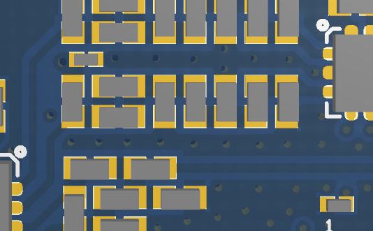
For an idea of how tight for space the layout is, here's a section of the layout. For reference the IC on the right is 2mm x 2mm, and there's about 0.175mm between the passives.
For the Antenna connections I'm a little torn between two options.
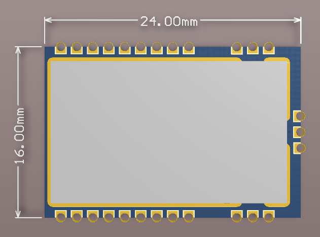
1. The three connections on different edges:
2. All three antenna connections on the far edge
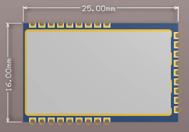
The first option is slightly smaller, but the second gives a little more space for components and routing and potentially makes routing easier on a carrier PCB. If there are any differences in RF performance I think they're marginal. I'm leaning towards the second option and overall pretty happy with the size of both.
Any thoughts, anyone?
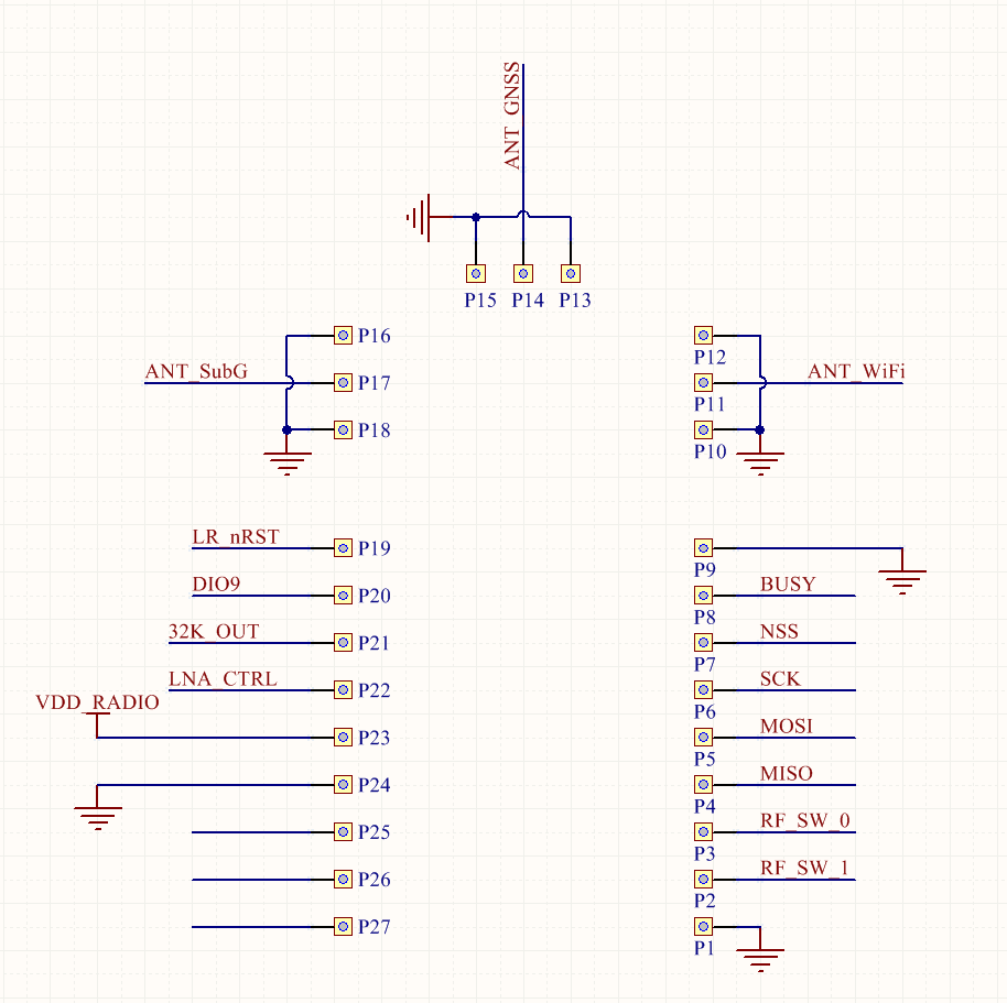
I've still to properly route the control signals to the side connectors. Once I finalise the antenna connector position I'll post an update with the pin labels too. There are a few less important things that I could break out; a 32KHz clock output, and GPIO (like the control line for the GNSS LNA and RF switch which are probably only useful for diagnostic purposes).
This is the pin-out for now, which will definitely change!
Discussions
Become a Hackaday.io Member
Create an account to leave a comment. Already have an account? Log In.