 Simon Merrett
Because I will be ordering some PCBs for work soon, I wanted to get this design finished in time to be lumped in with that batch. It struck me during layout that there's no way I should be leaping in with the time investment of the PCB layout and the expense of PCBs, which let's face it aren't in the cheap size bracket. What I really should do is make a small macro keyboard, test that I can get that working and then scale up to a proper keyboard afterwards. But then I thought if I do that, I won't find out all the physical issues with my keyboard until the second revision. So that got quickly forgotten and layout continued.
I have added the schematic to the files for interest. I'll do a separate log on that. It's backwards but I'm sure you can work out how to read logs in reverse sequence.
Big decision
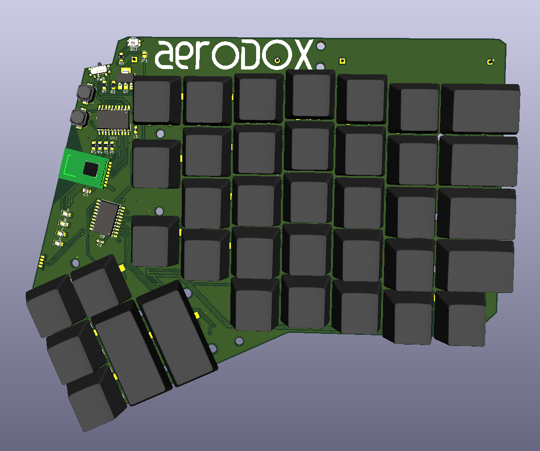
The main keyboard layout decision I made was to stick with the standard ErgoDox thumb cluster position and layout. I reasoned that if I deviate from this on my first attempt, I'll never know which direction to go if I don't like it. If I don't like the standard one, at least I'll be able to reference my experience to the multiple reviews of people who have also tried this layout. Rev 0.2 could consider making the thumb cluster electrically separate, to facilitate changing its position.
Matrix wiring
You may remember that I spent some time working on a reversible key switch footprint in kicad 5.1.2, using the custom footprints feature. In case it's not obvious, these split keyboards save you money on PCB fabrication if you make them reversible (flip it over and populate it to create the opposite half of your keyboard). One of the reasons I tried to use the custom footprint feature, rather than just putting multiple pads with the same number on the footprint, was that I hoped to save having to manually connect those pins together using traces on the main layout in pcbnew (if I wanted to be able to use the DRC and not get flooded with false "unconnected" errors). For some reason that I'm sure is very helpful and prevents people making big mistakes, if a copper section connects two pads with the same number on the same layer, kicad doesn't consider those pins connected and will place an airwire in the ratsnest to point this out to you. As far as I can tell, the custom pad feature doesn't fix this either. Sigh.
Nevertheless, making a more reversible footprint was worth it to me in the end - routing the key switches was the easiest part of this design. And if they work/fit, I'll be able to share the footprint to hopefully save other people some time too.
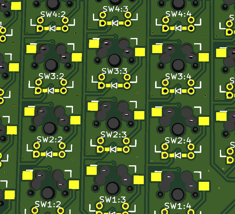
Note that I haven't populated the 3D file for a diode or the "hot swap" switch holders here, so you can still see the pads. Those "though hole" pads are not plated and there's a gap between the drill hole and the copper annulus. This is one of the things which allows this to be wired up both ways round. Hopefully.
Close up on the front
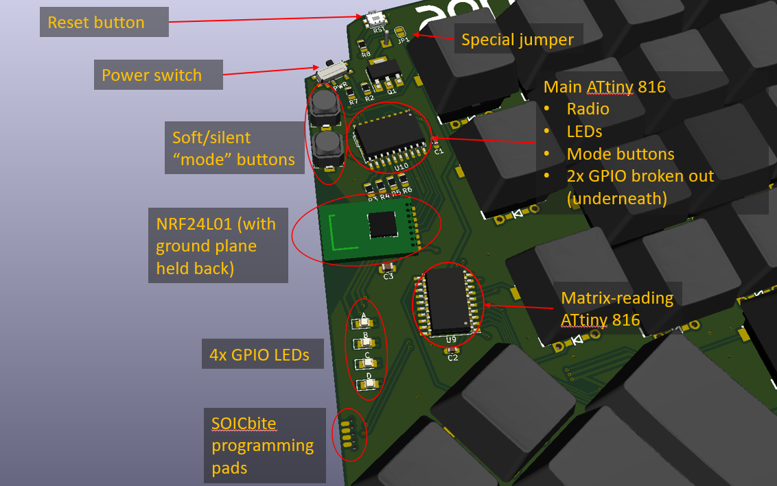
The special jumper is there to join the two reset pins for the two ATtinys to one reset button when programming is complete. You don't want to do this beforehand because the reset pin on an ATtiny 1 series chip is also its programming and debugging interface, courtesy of UPDI. So two UPDI pins connected to one programmer would no doubt get confusing! I did consider another jumper as I understand QMK firmware can use pin state to determine whether a chip represents the left or the right hand half of the keyboard. But we can use the GPIOs for this if we want to go down that route (the chance of QMK running on these ATtinys is next to zero - it's going to be running on the receiver end).
The mode select buttons are yet to be defined but they seemed like the best way for me to switch quickly between different computers. Increment on one button, decrement on the other, perhaps with LED flashes to enumerate. I must say I do like the ALPS SPKM buttons. I first saw them used as slient options on homemade Arduboys (presumably to allow gaming in bed with a partner?) and added them to my own WIP arduboy compatible game console. They have plenty of travel for a tactile switch but I'm a kbd noob, so I don't really know how to describe them to you (yet). But they're small enough not to get in the way:
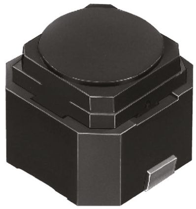 During the (inevitable) second board revision, there's every chance I'll think about swapping these for some right angle edge buttons like the reset switch. An edge mount button would be tidier, perhaps. But harder to integrate with cases that will more than likely come up the sides of the PCB.
I forgot to label it but just below the reset button is a P channel MOSFET and resistor as reverse polarity protection.
Batterys as tent supports?
The 2x AA batteries are mounted on the rear but I have selected a holder that doesn't have a spring as the negative contact, so putting the batteries in the wrong way round is a risk that I need to design out.
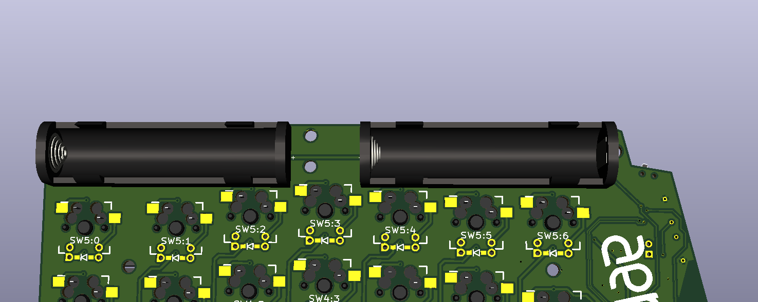
The 3D file (and footprint) is just scaled up from the AAA holders that ship with kicad 3D libraries. I didn't have a proper look for 3D CAD for the Keystone 1028 (or equivalent) that I plan to use, which definitely doesn't have the spring contact you see here.
The batteries are on the rear at the back because I think I'll likely want a slight tent on this keyboard (tent is what people call the angle they prop their keyboard up at?) and will have Z to burn at the back. I was hoping to install the battery holder contacts between the first (furthest away?) and second row of keys but sadly the column staggering didn't allow this. You see, I wanted to keep the battery holders in-line, so I have the option that the batteries form part of the support at the rear, so I didn't want to fiddle with their alignment. Maybe on Rev 0.2.
Talking of the support. I have laced the PCB with M3 holes, with somewhat round-number spacing and an intent to use 3D prints, standoffs and machine screws to work out what the best pose for these is.
Firmware optimism
Finally, I had a squiz at QMK to see if there was any way to harness it with this wireless link in the way. I think there may well be. The support for split keyboards looks like the key to me - the adaptation of #USE_I2C for GPIO expanders allows us to send a matrix of key states/changes to the main microcontroller. If I get an ATtiny receiving messages on the NRF24L01 and acting as an I2C slave, I think this could work with "almost" stock QMK.
Discussions
Become a Hackaday.io Member
Create an account to leave a comment. Already have an account? Log In.