 David Brown
1. Assembled board, 1 pot for adjusting zero level and one for adjusting the measured / current level
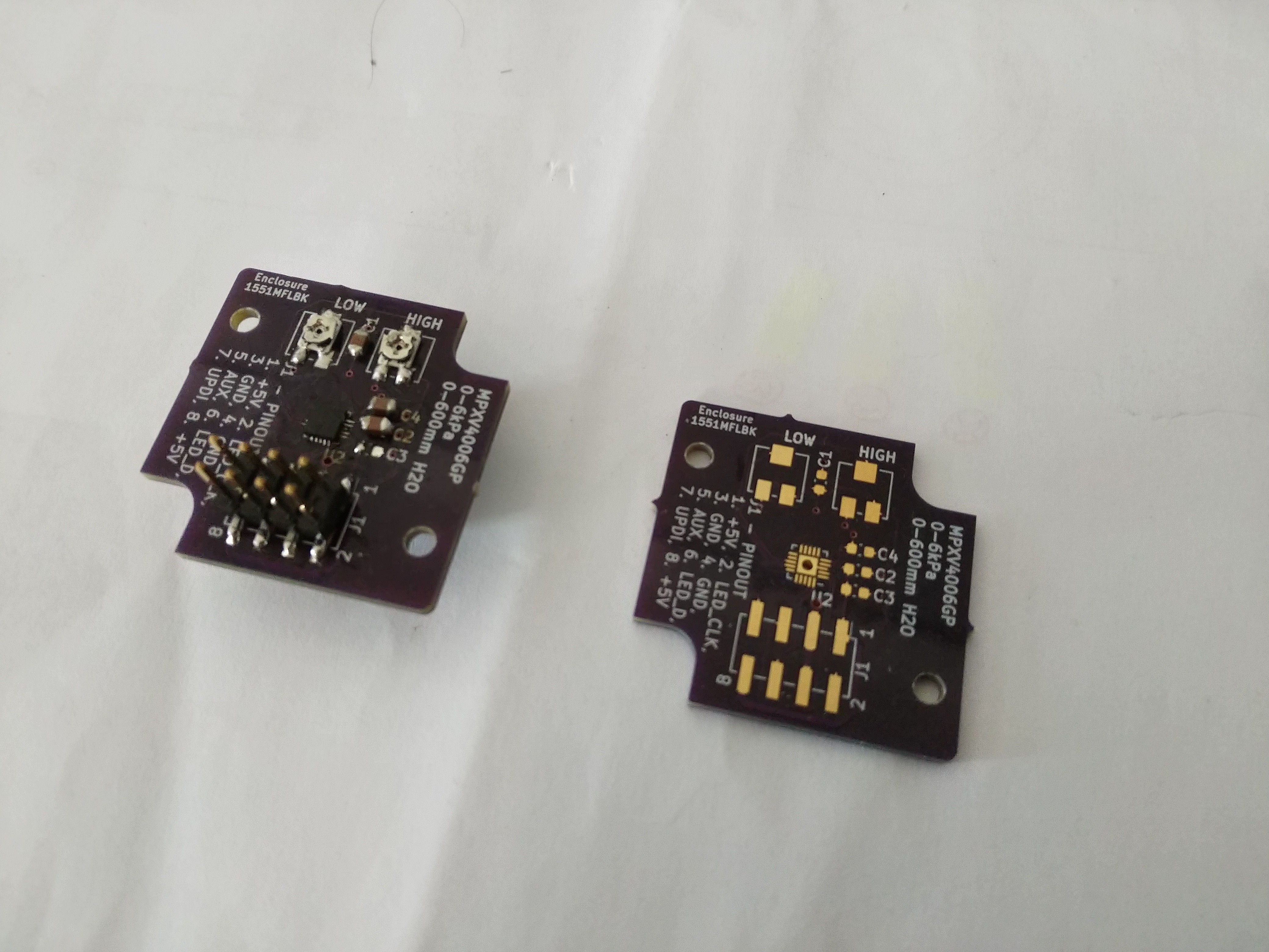
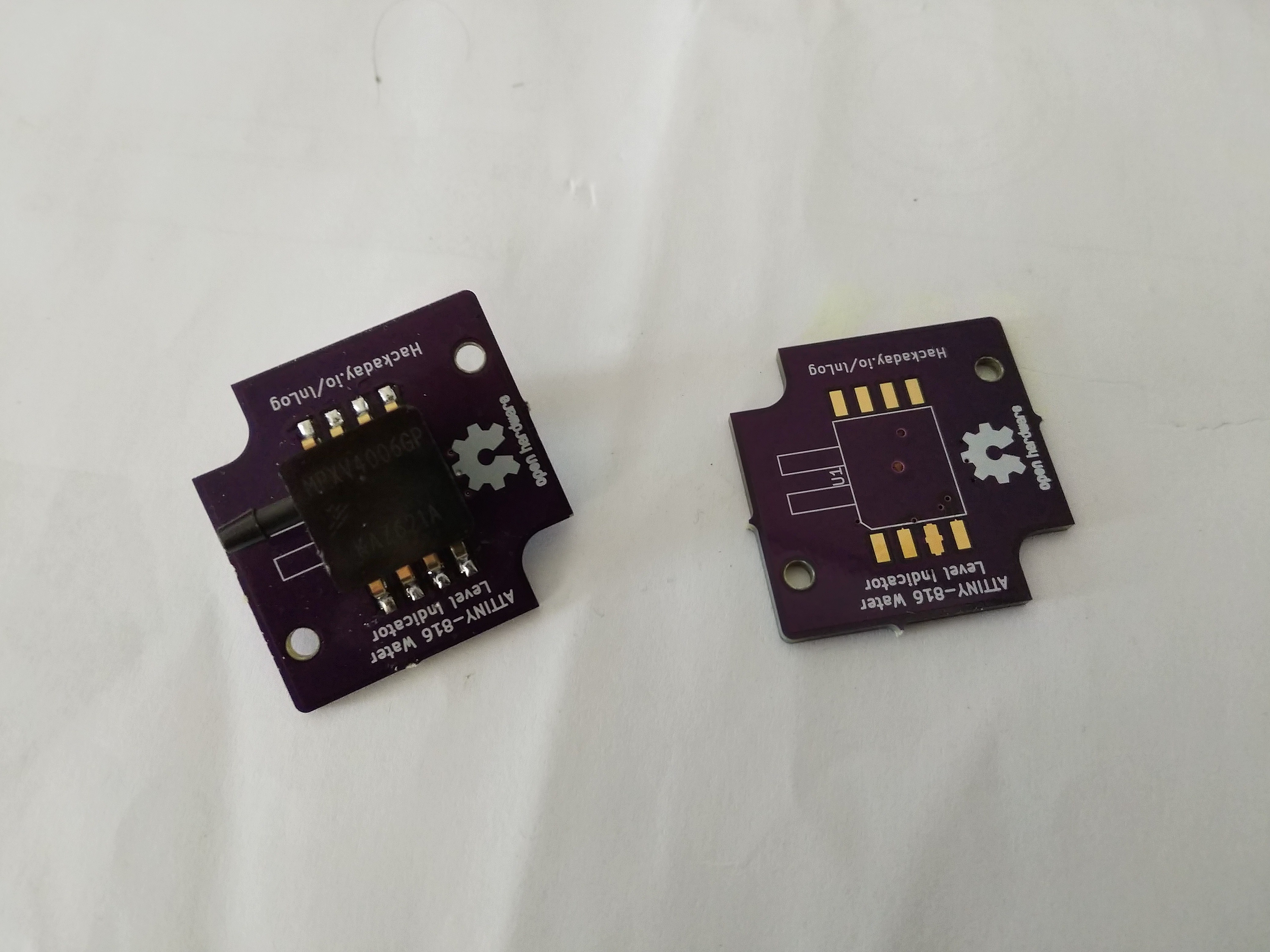
2. Showing the pressure sensor
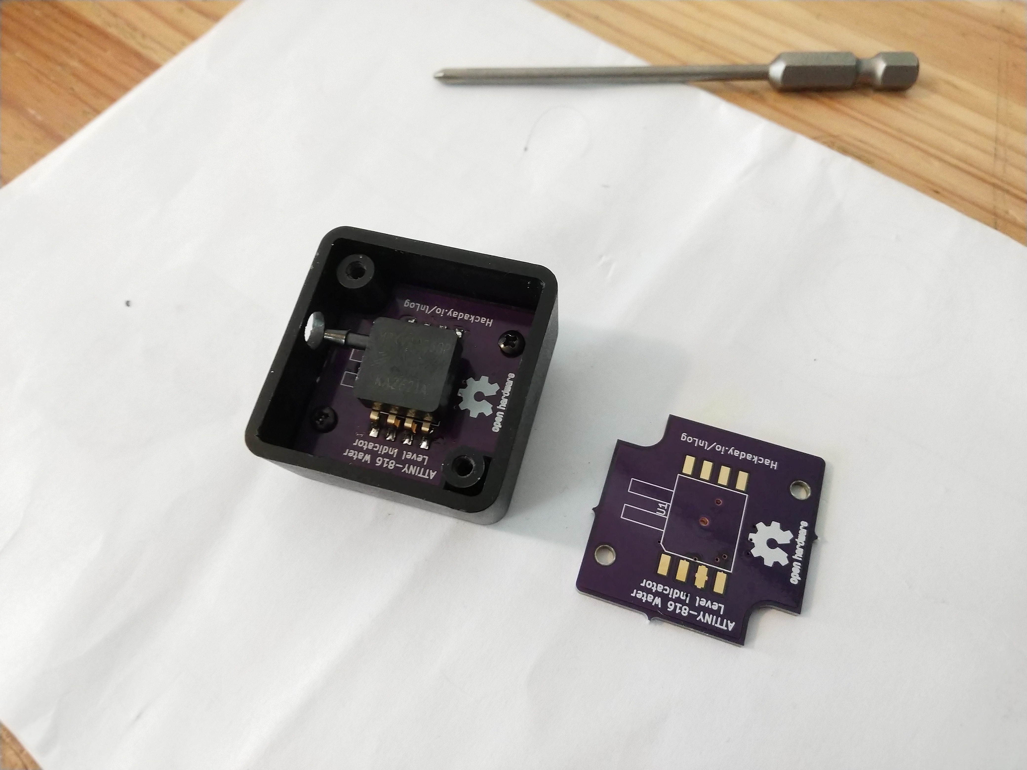
3. In the case
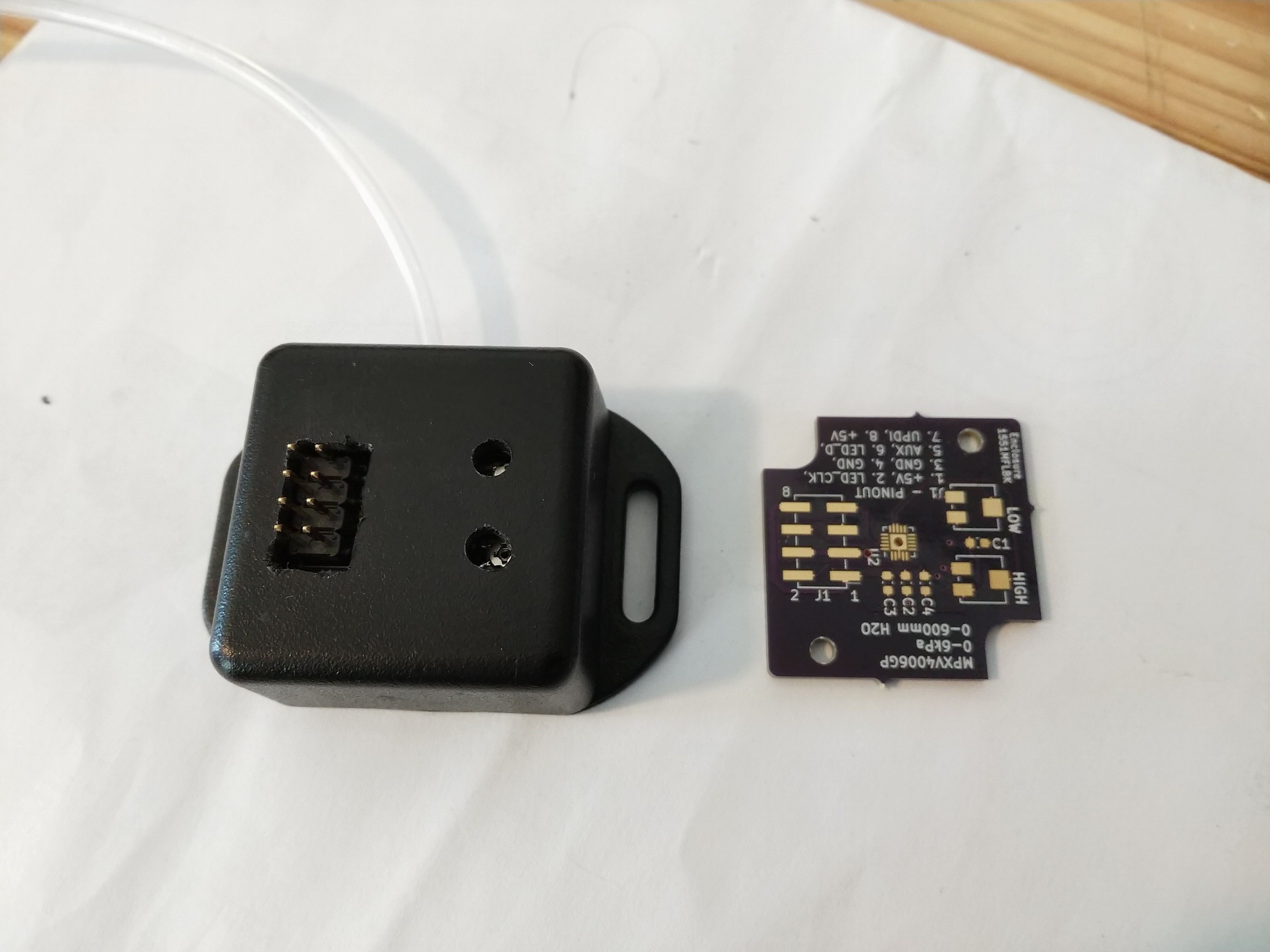
4. Outside, with pressure tube fitted
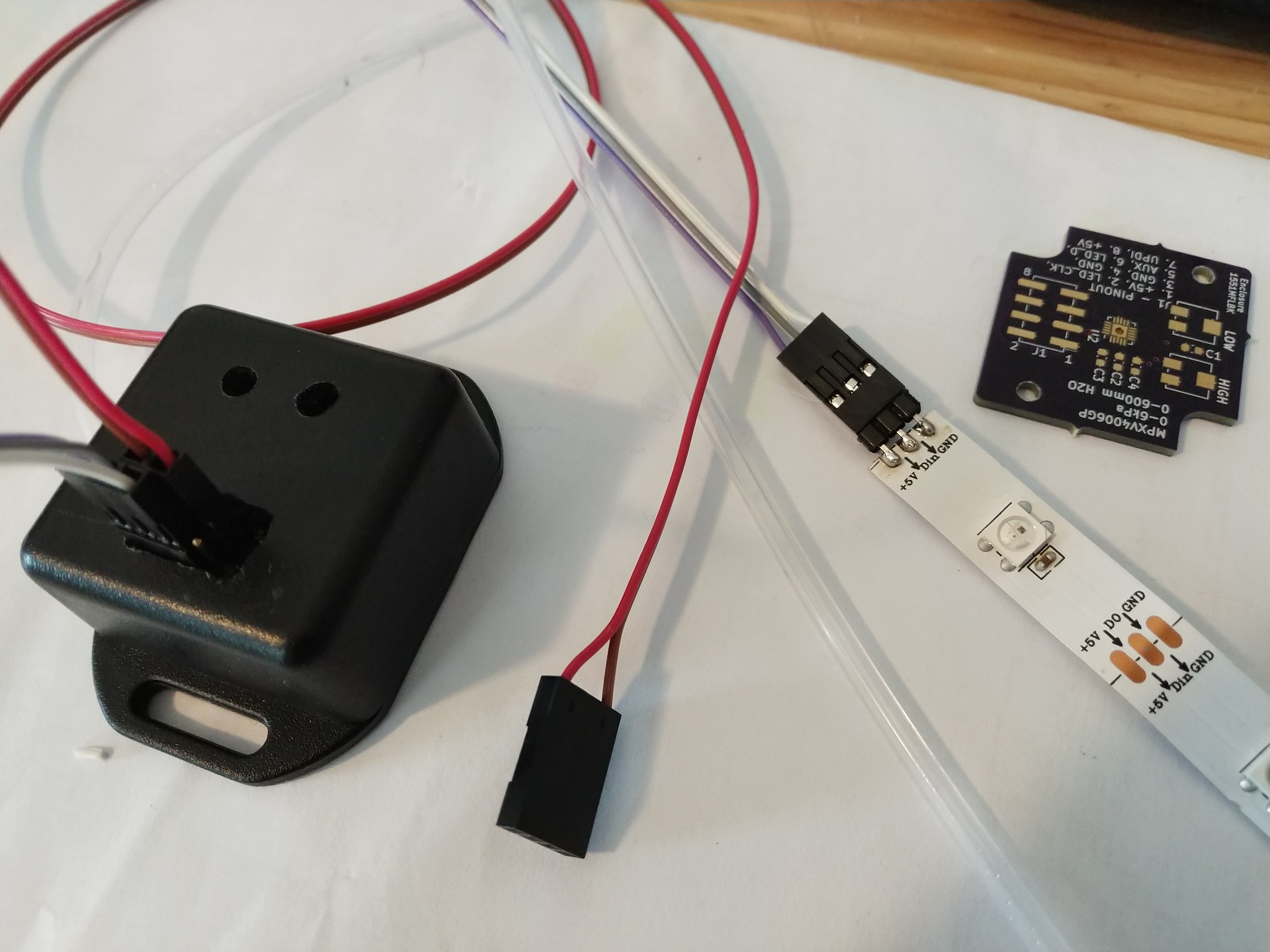
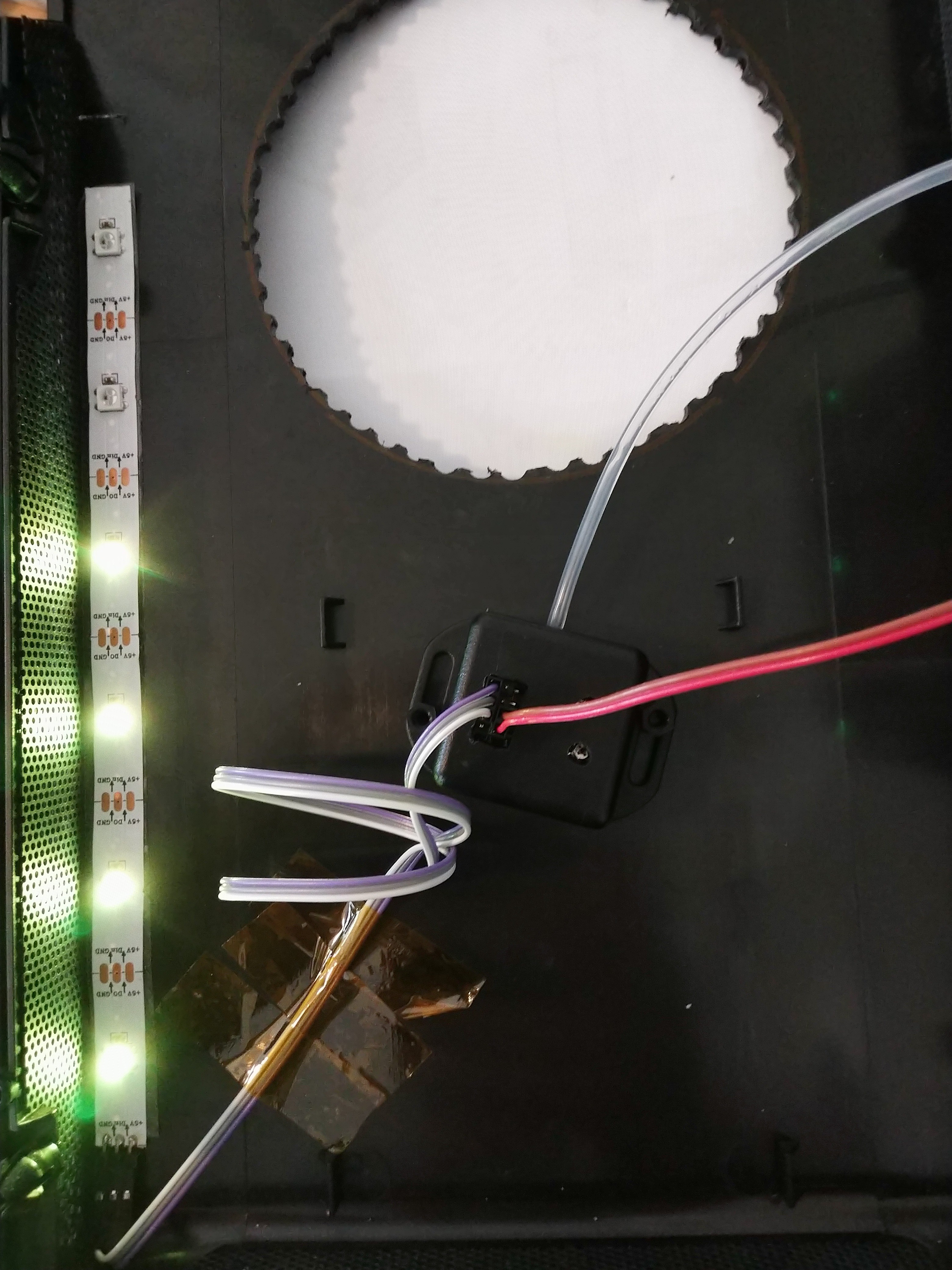
5. Assembled cables and LED strip
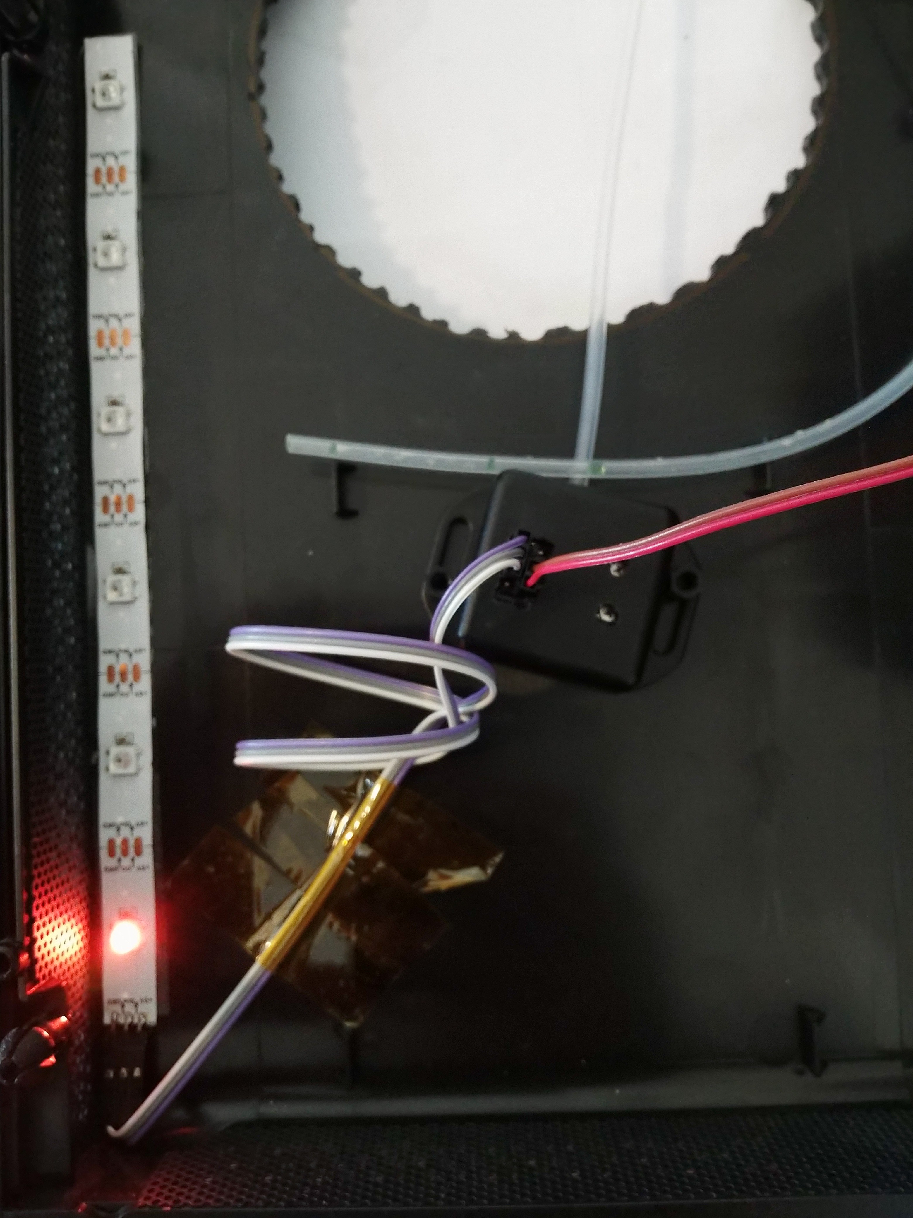
6. Uncalibrated, negative need to set the zero level pressure
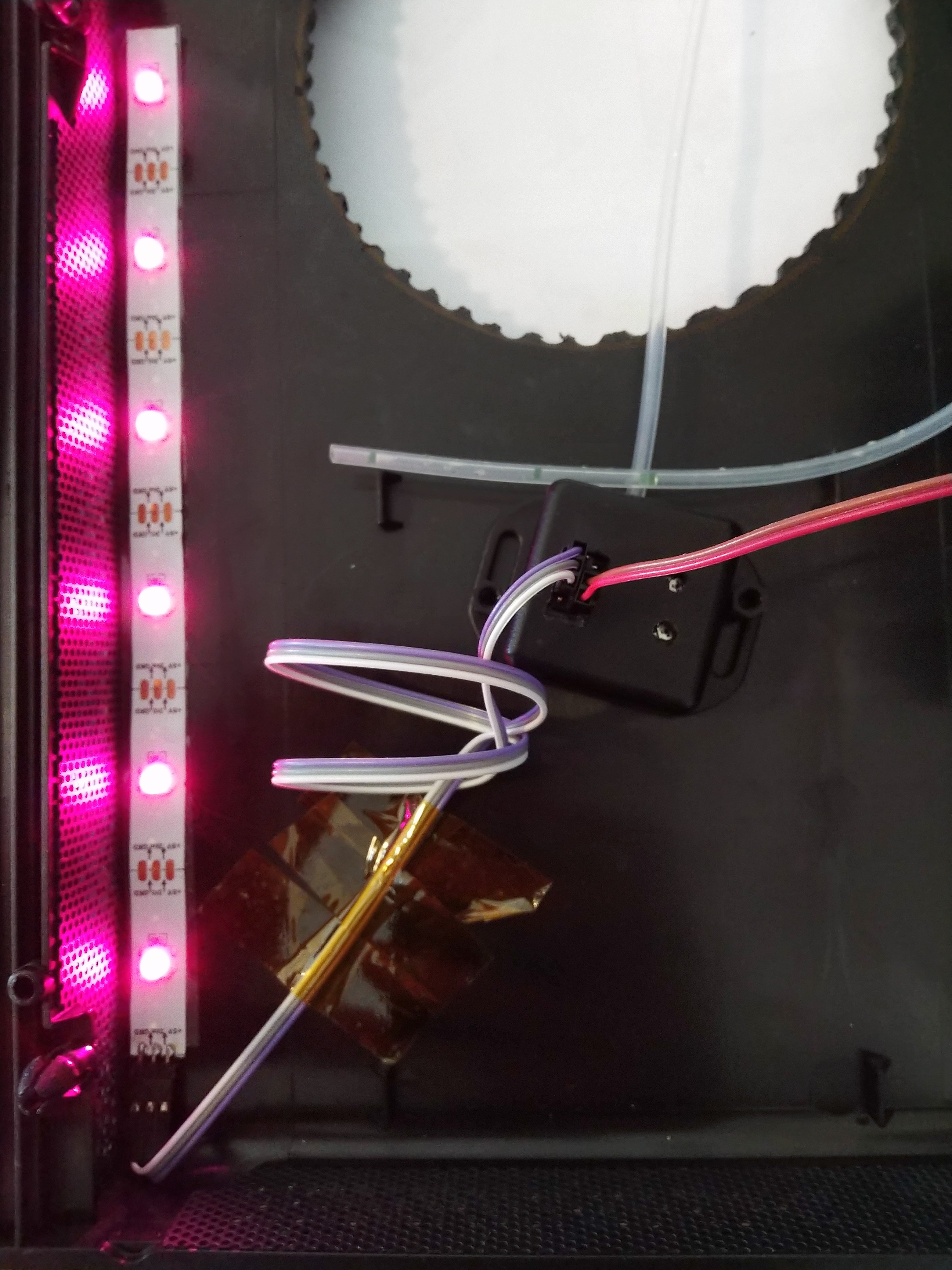
7. Zero level pressure set
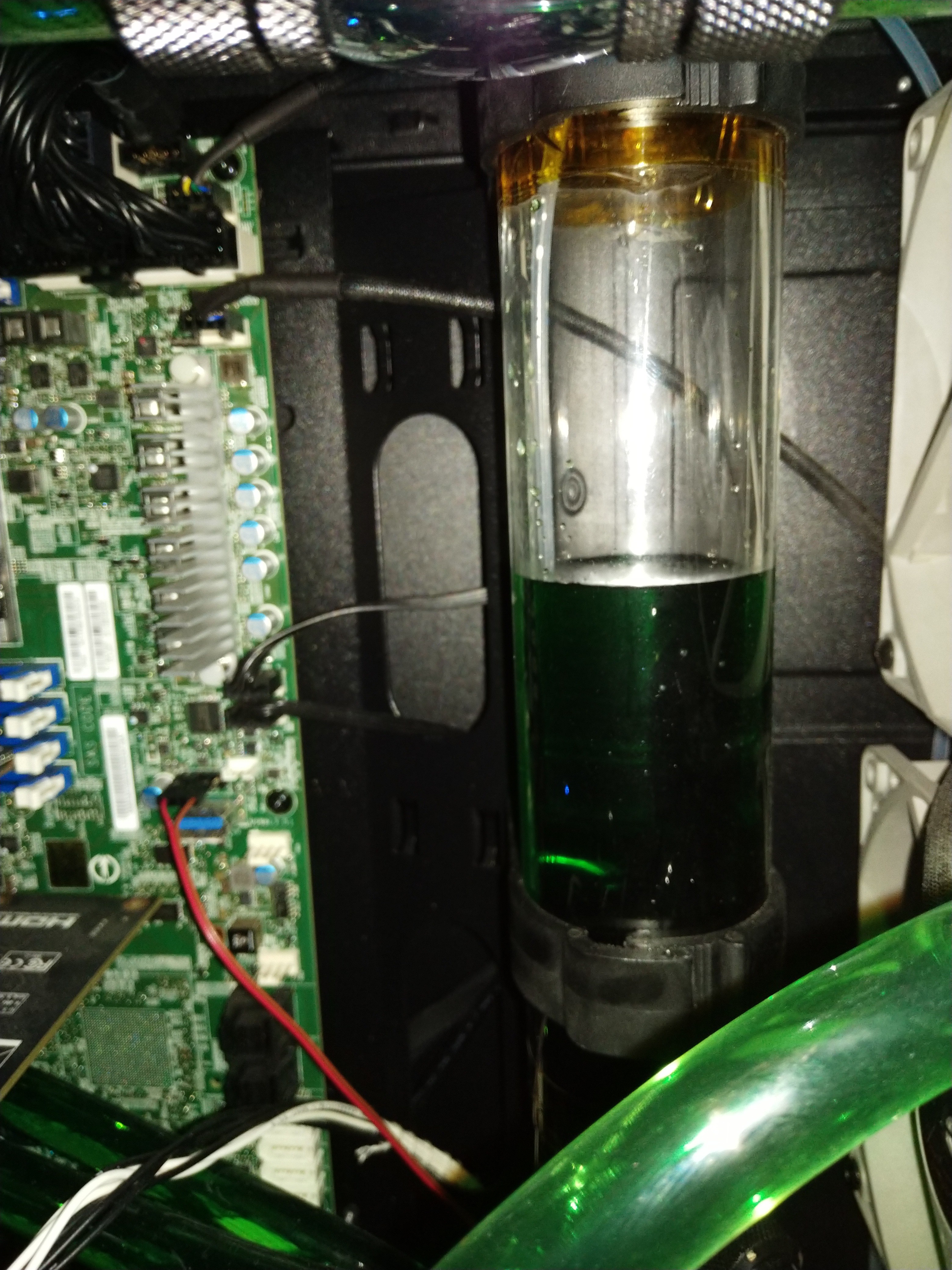
8. Resevoir with tube passed in from the top so the open end is at the bottom of the container. Because the static pressure is constant everywhere in the tube, the pressure measured at the sensor is the pressure at the open end - at the bottom of the water column.
9. Adjust the 'high' level pot so that the LEDs match the level in the resevoir
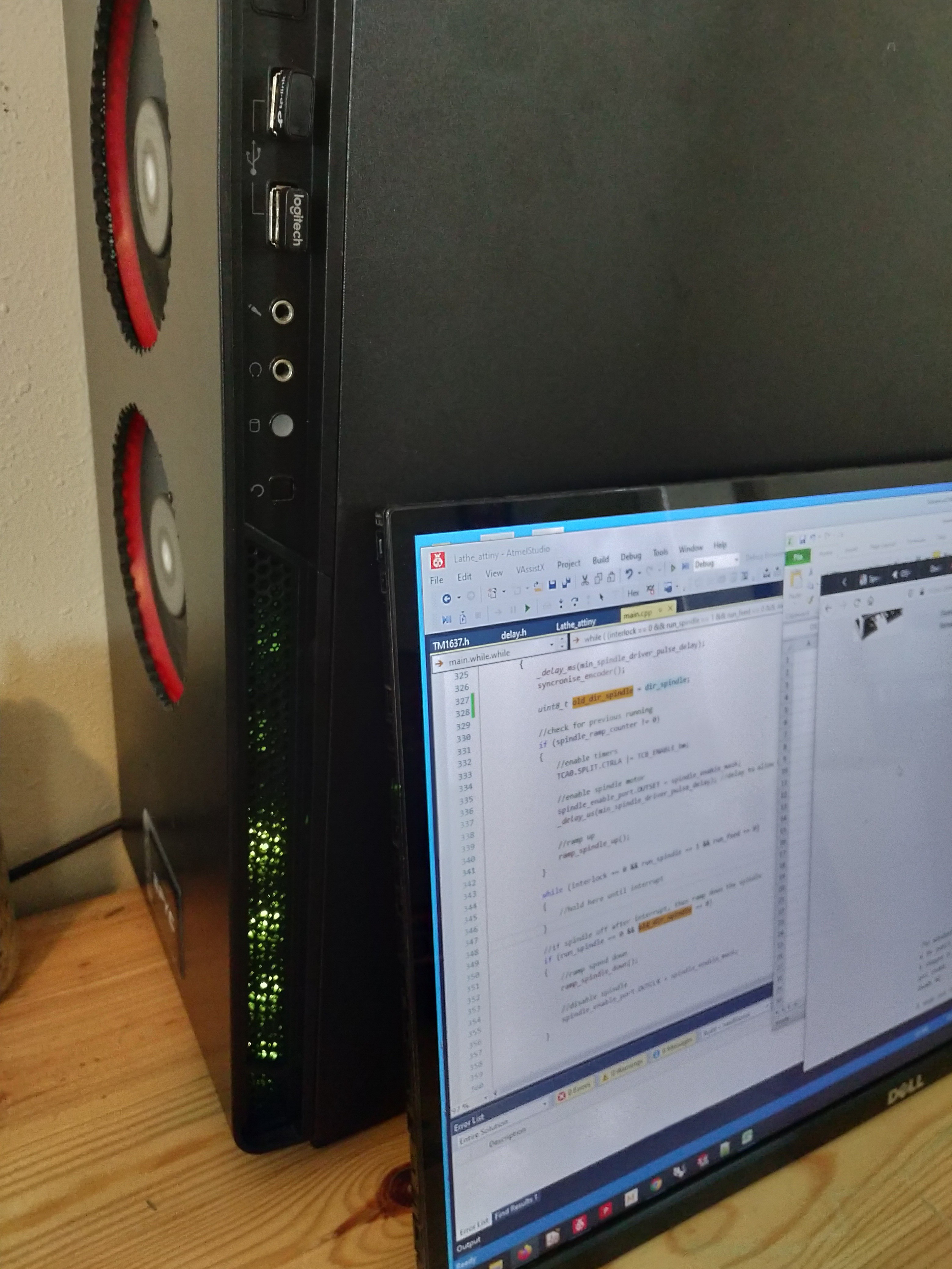
10. Assembled back into the case. Many options here for setting up the LEDs if you have a window case.
Discussions
Become a Hackaday.io Member
Create an account to leave a comment. Already have an account? Log In.