 Taylor Schweizer
I've written a bit about this on my website https://learn-cnc.com/reverse-engineering-pcbs/ and I'm going to use the same flatbed scanner for these.
Unfortunately some of the connectors and stuff on these parts were so large that the flatbed scanner couldn't image the traces, so I had to remove them. The scans of each side were about 1.6 GB each, so I downsampled and converted them to a PNG (they were a 24 bit BMP) which reduced them to about 80 MB each. Still large, but workable.
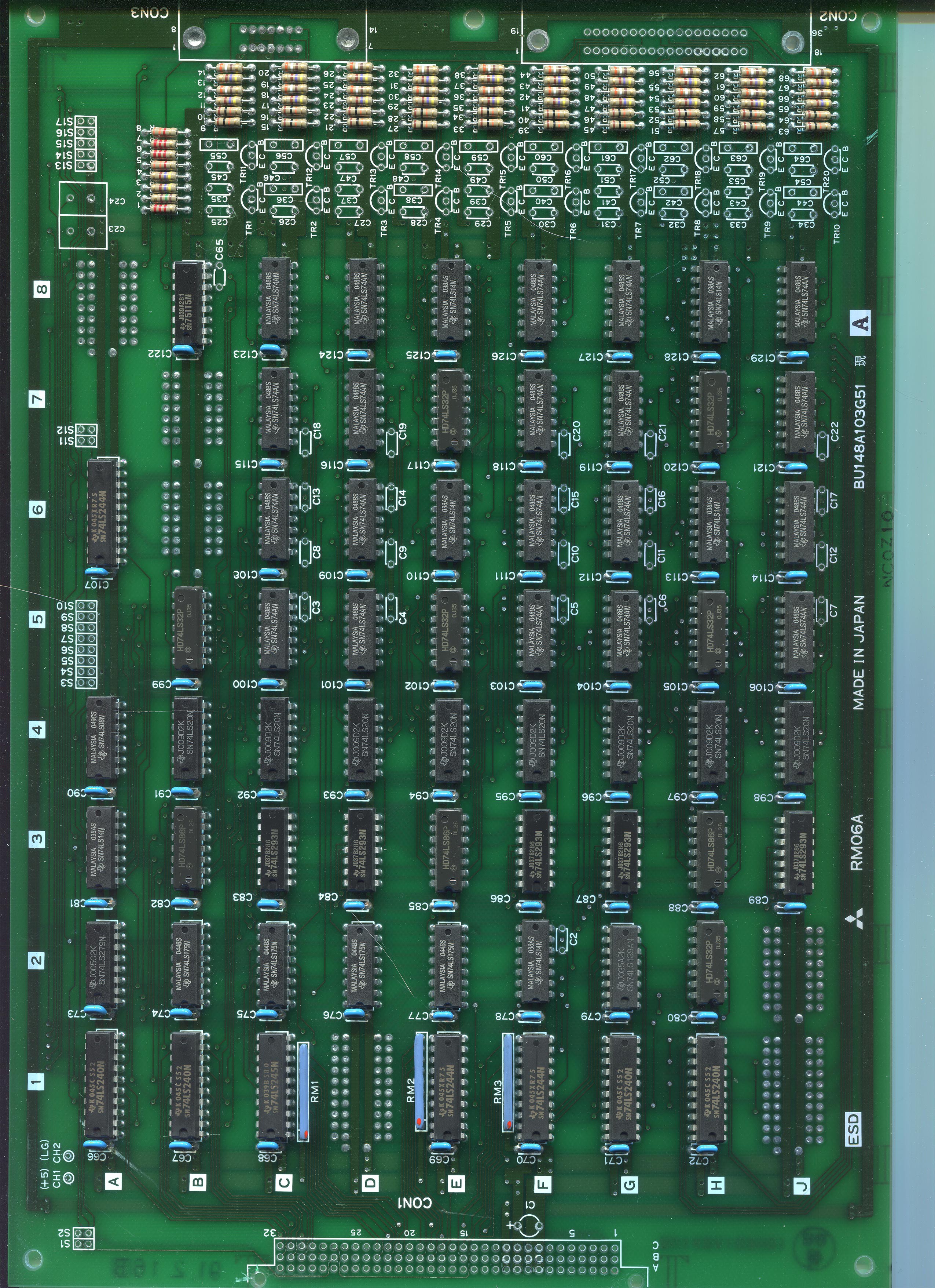
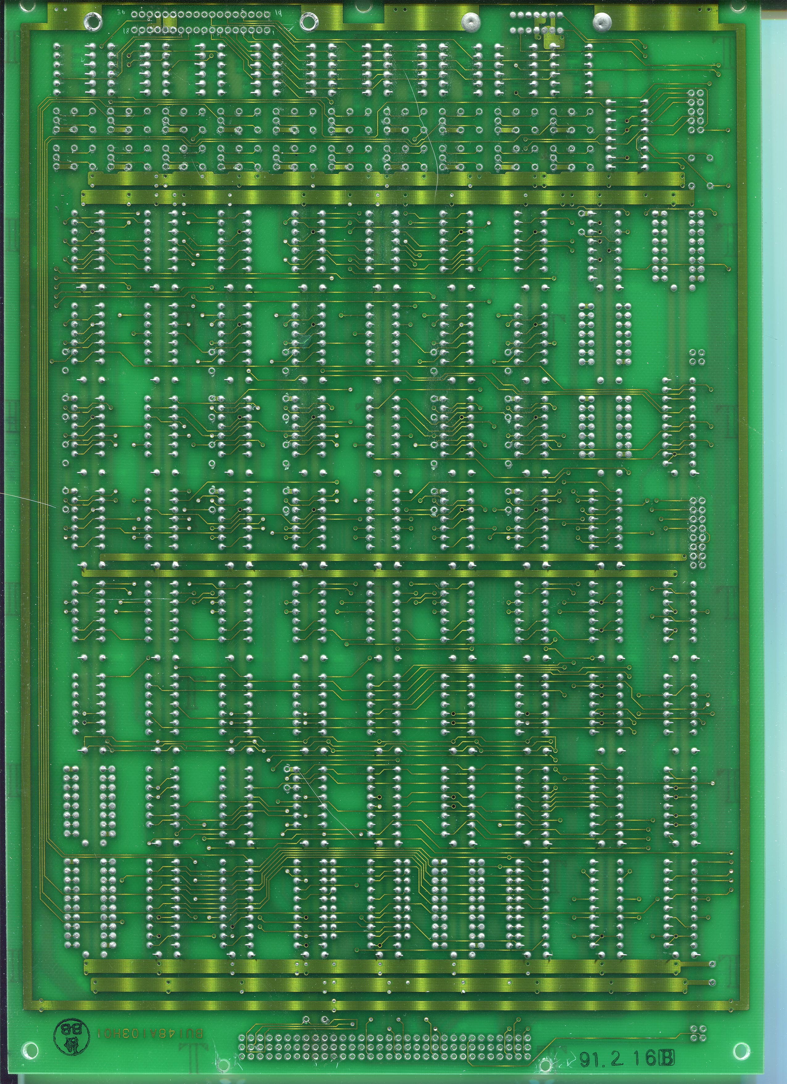
Here's some sample scans from the Motor Signal board (these have been further downsampled and compressed to a JPG, about 2 MB each):
I then use the perspective warp and crop tool in Photoshop to square up each image. This makes aligning them much easier. Then I make a new layer just for holes and vias so I can align the images using the warp tool.
I start by finding the ground and power rails since those are the easiest to find and cover the largest amount of traces and holes. On a smaller board I would remove every component, but I'm only planning on reverse engineering a single encoder channel since it looks like this is just a repeated circuit so I don't need all traces.
Discussions
Become a Hackaday.io Member
Create an account to leave a comment. Already have an account? Log In.