 Taylor Schweizer
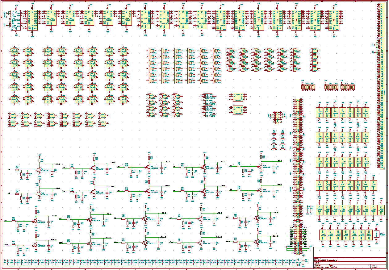
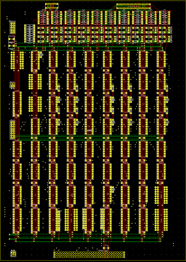
So I realized something - the entire board is laid out on a 0.100" grid. Every single pin of every part (besides two connectors that have a 0.085" pitch) is on that grid. And it lines up. Knowing this, I went back to photoshop and used this to make sure the board was square and exported a second hole layout, and re-layed out the entire board in KiCad. I also found that all of the vias were on a 0.050" grid, and the tracks on a 0.025" grid. This makes laying out much, much easier.
The reason I redid this was because there is a bit of a difficulty with the way I do reverse engineering - basically if the scan of the PCB doesn't result in a perfectly square image, there is usually a slant to the traces and pin layouts. To counteract that, I usually use a very small grid when running traces so I can run traces and stuff to accommodate the misalignment. But since everything is on the grid I mentioned before, I could make sure everything was aligned properly.
I also went ahead and added all of the power capacitors and various connectors and stuff. I'm already using an A2 size page for the layout, and I just about have it filled with the empty components. This is getting wildly out of control.
Discussions
Become a Hackaday.io Member
Create an account to leave a comment. Already have an account? Log In.