The lifting gas chosen for the proposed robotic airship platform is helium as it is safe and provides high lifting capacity. An alternative with comparable buoyancy is hydrogen, which was immediately discarded due to its high flammability characteristics. Hot air was also considered, but its lifting potential is significantly lower than that of the above gases. In addition, the heating element would pose a safety risk, especially for indoor use. Other lifting gas choices are either toxic, flammable or offer minimal buoyancy, making them inappropriate for this application.
A. Envelope Material
Before designing the gondola, a number of envelope material candidates were examined with respect to their helium permeability and mechanical properties. To ensure a low cost platform, the envelope was chosen from the following set of commercially available balloons (see Figure 2):
- Qualatex untreated round 41 cm (16 inch) latex balloon
- Qualatex untreated round 61 cm (24 inch) latex balloon
- Qualatex round 61 cm (24 inch) latex balloon treated with Ultra Hi-Float (UHF) [25]
- Qualatex 61 cm (24 inch) clear Bubble balloon (layered membrane including a high barrier layer of ethylene vinyl alcohol copolymer)
- Qualatex round 91 cm (36 inch) Microfoil (metallised PET) balloon
Evaluated balloons, from left to right: Qualatex untreated round 41 cm latex balloon, Qualatex untreated round 61 cm latex balloon, Qualatex round 61 cm latex balloon treated with UHF, Qualatex round 61 cm Bubble balloon and Qualatex round 91 cm Microfoil balloon.
To evaluate their helium permeability, the balloons’ lifting capacities, along with their surfaces, were measured daily over the course of 16 days. Because of their elastic properties, the surfaces of latex and Bubble balloons were determined through their circumferences. The Microfoil balloon surface was measured before inflation as the material does not stretch. After collection, the helium escape rate was computed as the flux through the balloon envelope, given by:
where J is the gas flux, Q is the amount of gas escaping, t is time and A is the envelope surface. The obtained helium escape rates were then averaged and used in a feasibility study projecting expected helium losses through the membrane of an ideal spherical balloon. The approximate cost of helium used in the study was based on commercially available balloon gas tanks.
The mechanical properties of latex, Bubble and Microfoil materials were examined in terms of membrane thickness in the inflated state, membrane area density in the inflated state, membrane tensile strength, and membrane elongation characteristics. Material samples for latex were taken from the Qualatex untreated round 61 cm balloon. For the Microfoil balloon, thickness was measured in the uninflated state because the material stretching is negligible during inflation. As the latex and Bubble balloons stretch during inflation, their inflated membrane thickness ti was estimated by assuming constant density of the material:
where tu is the uninflated membrane thickness, Au is the uninflated balloon surface, and Ai is the inflated balloon surface. The area density for all balloons was computed from the uninflated balloon mass and inflated balloon area. Material tensile strength and elongation were obtained experimentally, in accordance with the ASTM D412-16 Standard [26] for latex, and ASTM D882-18 Standard [27] for the Bubble and Microfoil materials. Samples were cut with the Standard Die C, as per ASTM D412-16 for all materials. The strain rate was 50 mm/min for Microfoil, and 500 mm/min for latex and Bubble samples. For each material, five samples were tested.
B. Gondola Design and Placement
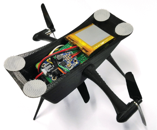
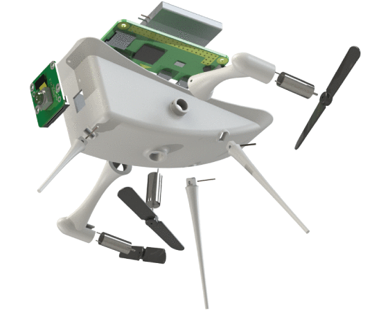
The airship gondola was built around the chosen electronic components and actuators. The central control and communication unit is a Raspberry Pi Zero W running a Lite version of the Raspbian Stretch operating system. Peripheral components include a single cell 500 mAh Li-Ion battery, step-up voltage regulator, motor drivers, three 7x16 mm DC motors, three 57x20 mm propeller units and a camera module that will facilitate the formulation of HRI frameworks. Rotor speeds can either be controlled by on-board logic or manually via a wireless connection through SSH or an appropriately developed Robot Operating System (ROS) package [28]. The combined cost of the gondola components (excluding the 3D printing filament and wiring) comes to 90 USD, which drops to 54 USD if the camera module is not required. Parameters for all subsystems of the robotic airship, including component descriptions, product codes, prices, and links to reseller webpages are collected in a bill of materials available through the website listed in the Conclusion.
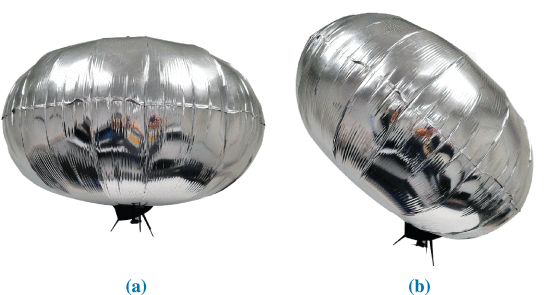
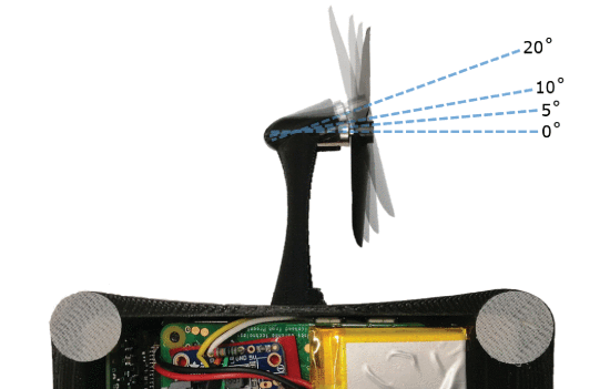
The physical frame is 3D printed and built in a modular fashion: the gondola legs and rotor brackets were detachable to facilitate component modification and replacement. The assembled gondola and its exploded view model are presented in Figures 3 and 4, respectively. The gondola is attached to the chosen envelope using Velcro. The gondola placement on the chosen envelope and the rotor angles with respect to the horizontal axis of gondola symmetry were determined experimentally to optimise flight stability. Two gondola placement options were considered. The first placement was centered and symmetric with respect to the envelope, in which case the side rotors were horizontal and a third one would in principle be required to control the airship altitude (Figure 5a). The second option angled the gondola with respect to the envelope centre, tilting the airship and shifting its side rotors out of the horizontal plane (Figure 5b). In this configuration, the airship orientation and altitude could be controlled using only the two side rotors. The side rotor angles of 0°, 5°, 10° and 20° were examined in the experiments. The four evaluated rotor angle configurations are depicted in Figure 6. The experiments consisted of 10 trials for each rotor angle and gondola placement at 25% and 50% of the rotor maximum speed (160 trials in total). The airship was released from a height of 1.5 m. During flight, the airship position and rotation were recorded with the Vicon motion optical capture system, which consists of 8 Vicon T-series cameras connected to the Giganet system. The Vicon Tracker software was used to capture the trajectories of reflective markers mounted on the airship envelope. The system sampling rate was 100 Hz.
C. Proof-of-Concept Path Following
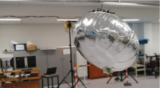
The airship was evaluated in terms of its path following ability in an indoor environment. The angled gondola placement (Figure 5b) with 5° rotor angles was used in the experiments. Path following was implemented using a discrete variation of the carrot-chasing algorithm described in [29]. Because the two side rotors affected the airship’s altitude in addition to its speed and heading, the algorithm was modified with a P controller that adjusted the baseline rotor speeds depending on the platform’s current altitude.
The implemented computational flow of the modified carrot-chasing path following algorithm is presented in Method 1, where ( x, y, z ) is the current airship position, ψ is its heading (yaw) angle, W0…n is the desired path segmented into a sequence of equidistant waypoints, Nt is the look ahead index, zt is the desired altitude, Pψ and Pz are the heading and altitude gains, Cbase is the default rotor control signal and Cmin, Cmax are the minimum and maximum allowed rotor values. The method outputs control signals for the left and right rotor cl and cr . The proposed airship relies on two rotors for both altitude and heading control for simplicity reasons. This choice imposes certain instability to the platform. Multiple basic control methods that are typically used in undergraduate Engineering courses were examined and a basic proportional control provided the best results in terms of path tracking efficiency and simplicity. Other, more sophisticated methods can also be used, which is a matter of future research from users of the proposed device. The framework was implemented as a collection of nodes within the ROS architecture, which provided the basic communication utilities and allowed for easy debugging. The airship real time position and orientation were continuously published by a node tracking the airship, which was connected to the Vicon data stream. It ran on a personal computer, along with a node running the path following algorithm and publishing the rotor control signals with a rate of 5 Hz. The airship was running a single node that was receiving the control signals and setting the desired rotor speeds. For this application, the path following and rotor control nodes were written in Python. The airship node running on the Raspberry Pi Zero was communicating with the rest of the system through Wi-Fi, on a dedicated local network. The associated communication latency was in the range of approximately 3 ms, which has proven to be sufficiently low for the proposed application. The system was tested on a circular path with a diameter of 4 m and waypoint spacing of 10 cm. The target altitude z t was set to 1.8 m, with a gain of Pz = 25 . The base rotor control signal was set to Cbase = 53 on a scale of 0 to 255, while Cmin and Cmax were set to 30 and 255, respectively. The look ahead index N t and heading gain P ψ were manually tuned with the goal of minimising the cross-track error. Position and orientation of the airship during path following was recorded and examined.
References
[25] "Gas barrier coating and coated elastomeric toy balloons", Sep. 1993.
[26] ASTM, D412-16, "Standard Test Methods for Vulcanized Rubber and Thermoplastic Elastomers—Tension", 2016.
[27] ASTM, D882-18, "Standard Test Method for Tensile Properties of Thin Plastic Sheeting", 2018.
[28] M. Quigley, K. Conley, B. P. Gerkey, J. Faust, T. Foote, J. Leibs, et al., "ROS: An open-source robot operating system", Proc. ICRA Workshop Open Source Softw., pp. 5, May 2009.
[29] P. B. Sujit, S. Saripalli and J. Borges Sousa, "Unmanned aerial vehicle path following: A survey and analysis of algorithms for fixed-wing unmanned aerial vehicless", IEEE Control Syst. Mag., vol. 34, no. 1, pp. 42-59, Feb. 2014, [online] Available: http://ieeexplore.ieee.org/lpdocs/epic03/wrapper.htm?arnumber=6712082.
 New Dexterity

Discussions
Become a Hackaday.io Member
Create an account to leave a comment. Already have an account? Log In.