A. Envelope
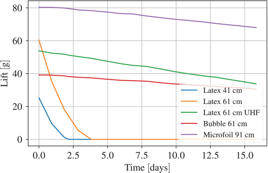
From the raw balloon lift measurements (Figure 7), it is visible that the untreated latex balloons lost their lifting ability in a matter of days, while others were deflating linearly at a much slower rate. A more direct material comparison was possible through determining the helium flux through the balloon membranes. To accommodate the experimental data, the helium flux equation was converted into an approximate, discrete form:
where Δ Q was computed from the daily lift loss and Δ t was the time between measurements. The amount of gas escaping Q was defined as the volume of helium at standard temperature and pressure (STP), according to IUPAC which defines them as T S T P = 273.15 K and p S T P = 10 5 P a [30]. Assuming that helium behaves like an ideal gas, the actual escaped gas volume V a can be converted into V S T P according to the ideal gas law:
Because the balloons were kept in a laboratory environment at sea level, the actual pressure and temperature were assumed constant at pa = 101.325 kPa and Ta = 293.15 K Assuming the pressure difference on the balloon membrane was negligible, the helium lifting capacity lHe in the laboratory environment was computed as:
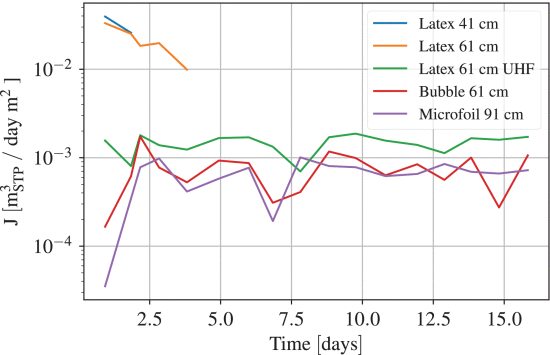
where m is the lifted mass and Va is the helium volume at laboratory conditions. The lHe for the used balloon grade helium was experimentally determined to be 0.95 kg/m3 from the latex balloon volumes, lifts and masses. Combining the above, the daily helium escape flux through the balloon membranes was computed (Figure 8).
Examining the obtained results, it is immediately visible that untreated latex is the least appropriate for an airship application. The helium was lost through the porous material in a matter of days and latex itself ages with time and UV exposure. Latex treated with UHF exhibits substantially better helium retention properties, comparable to those of the Bubble and Microfoil balloon materials. However, even UHF treated latex is subject to aging and easily bursts on impact with a rough surface. The Bubble and Microfoil balloons performed equally well in terms of helium retention, although an issue with Bubble balloons is their availability in terms of different sizes. For the experiments, the largest available Bubble size was selected and it could only lift 40 g at maximum inflation. While this might be enough for an optimised solution, it did not suffice in the prototyping stage. The helium escape flux measurements were averaged over the experiment period and collected in Table 1, where values for untreated latex balloons were merged. The table also presents the daily and yearly helium losses through the membrane of a spherical balloon that has a diameter of 60 cm corresponding to a surface of A = 1.13 m 2 . The flux values in the first row present the helium loss per day and per square meter, while the daily and yearly rates demonstrate the actual helium loss through the balloon membrane. Using approximate retail balloon gas costs, the yearly expenses of compensating the lost helium were computed (note that the yearly costs do not include the initial cost of filling the balloon, which is 16.5 USD). Examining these yearly cost projections, it is evident that helium related maintenance of an indoor airship is cheap, given an appropriate choice of envelope material. Such platforms are thus feasible from an environmental and financial standpoint.
Concerning the mechanical properties of evaluated materials (Table 2), the bubble balloon stands out with a roughly 20% lower area density, which converts to a higher payload for equal envelope volumes. The latex balloon was found to have a comparably low tensile strength, as well as an elongation of over 800 %, which is due to the material’s considerable thickness in the uninflated state. The Microfoil material was measured to have highest tensile strength with minimal spread, as well as a comparably low elongation. Since the proposed platform is not intended for high altitude operation, the envelope does not need to withstand extreme pressure and temperature changes. Instead, the critical material characteristic is its area density, which greatly influences the payload in cases where size is a hard constraint. From a mechanical aspect, the Bubble material would thus be most appropriate, with lowest area density and suitable material strength. However, the maximum achievable payload with a commercially available Bubble balloon is too low (40 g), and manufacturing custom envelopes would significantly increase the platform cost and reduce accessibility. The chosen envelope for this application was therefore the 90 cm Microfoil balloon, with excellent helium retention capabilities, high enough payload, and appropriate material strength characteristics.
B. Gondola Placement and Rotor Angles
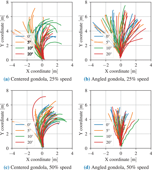
The experiment results are presented in terms of the airship horizontal XY position (Figure 9) and its yaw (Figure 10) during flight. Examining the figures, it is evident that the angled gondola offers greater flight stability than the centered option in the open loop. With the centered gondola, the airship tends to drift and turn right in most of the trials, which is even clearer at higher rotor speeds. With the angled gondola, airship flight is much more stable and its heading oscillates around a mean value instead of diverging. Even though the drifting present in the centered gondola experiments is likely a result of unbalanced thrust in the open loop, it is still evident that the angled positioning is more robust to such disturbances. This increased robustness is likely a result of air flow dynamics around the asymmetric shape of the angled solution, although a dedicated aerodynamic analysis would be necessary to determine the exact cause. In addition to its disturbance robustness, the angled solution was interesting also because it allowed altitude and heading control using only the two side rotors, reducing the overall gondola weight. The varying rotor angles were not found to have a large impact on the overall airship behaviour in straight-line flight. However, in the case of the angled gondola, larger rotor angles tend to cause higher frequency oscillations of the yaw angle (Figure 10b and 10d). In addition, higher rotor angles seem less appropriate also because they waste a portion of their thrust negating each other.
C. Proof-of-Concept Path Following
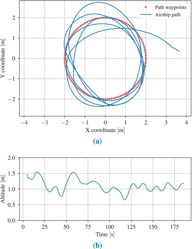
In this proof-of-concept application, the control parameters were found manually, as could be the case in basic design and control courses, where modelling and simulation are typically not part of the curriculum. Through the manual optimisation of the look ahead index and heading gain parameters presented in Methods, it was found that the values N t = 11 and P ψ = 50 produce a reasonably low cross-track error and stable path following behaviour (Figure 11a). As the distance between path waypoints was set to be 10 cm, the N t value of 11 means that at every position on the path, the airship attempts to direct itself towards the waypoint that is 1.1 m ahead. The airship’s altitude during path following exhibited some oscillations (Figure 11b), but there was no collision with either the floor or the ceiling of the motion capture laboratory. The recorded altitude is lower than the goal (1.8 m), which was expected considering the fact that it was regulated by means of a simple proportional controller. Overall, the path following experiments showed that simultaneous heading and altitude control using only the two rotors is indeed feasible. The results were not ideal in terms of cross-track error and oscillations in the airship altitude, but that is due to the fact that the chosen controller was not optimal for this setting and its parameters were determined manually. This experiment was conducted for proof-of-concept educational purposes.

References
[30] M. Nič, J. Jirát, B. Košata, A. Jenkins and A. McNaught, IUPAC Compendium of Chemical Terminology, Oxford, U.K.:Blackwell, 2009.
 New Dexterity


Discussions
Become a Hackaday.io Member
Create an account to leave a comment. Already have an account? Log In.