 rand3289
I made a gearbox with about 29:1 ratio that drives the spine shaft of the robot. It contains two 58:11 teeth gear sets reducing the RPM and increasing the torque. The gearbox has 3 3D printed axles supported by 6 ABEC-7 608zz bearings. All gears have a 1.3 mm module. Cad files are available for download.
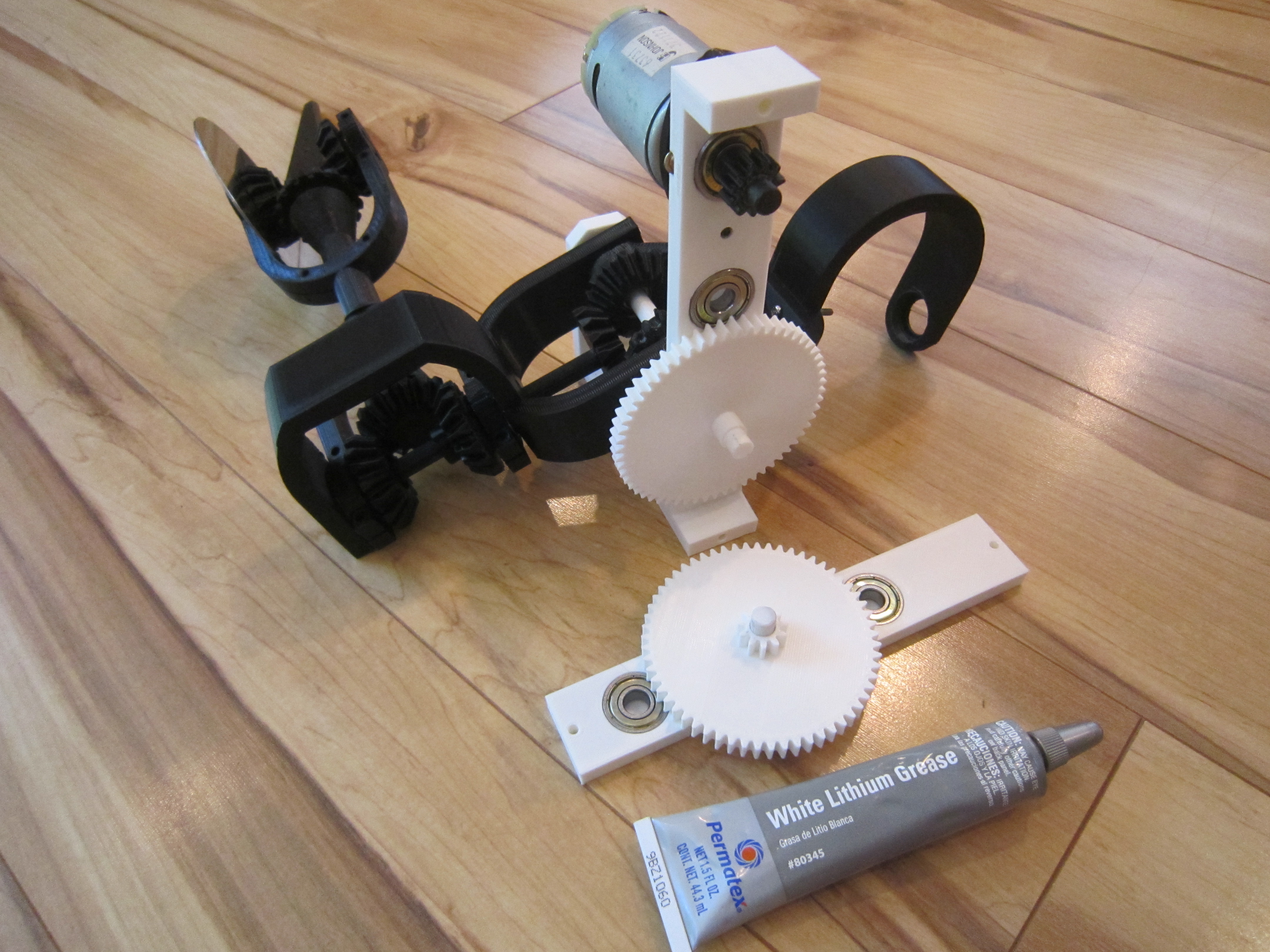
I am using a Johnson DC motor rotating at 14000 RPM and consuming 0.7A @ 13.8 VDC without a load. When installed in the robot the motor spins at about 13000 RPM (calculated) and consumes 1.2-1.3 A @ 13.8 VDC. The motor runs directly from a 2.5 A power supply. Disks spin at around 450 RPM one way, as measured by my PYLE laser tachometer and about 520 RPM the other way ( reverse DC polarity ). This is a bit high. Ideally I want under 300 RPM at the disks. This thing is loud and exhibits vibrations. After 10 min of continuous rotation the motor got hot to touch. Motor gear (first gear) and its bearings got a bit warm. All other parts remained cold.
As a result I do not recommend using the gearbox to reduce motor speed. It is best to use a commercial geared DC motor with output shaft speed under 300 RPM. Use a belt or 1:1 gears to connect the motor output shaft to the spine shaft within the gearbox. A small gear on the spine shaft will eliminate the reduction. (see gearBoxOneToOneGear.zip)
Discussions
Become a Hackaday.io Member
Create an account to leave a comment. Already have an account? Log In.