 Joseph Eoff
I use an ancient Telequipment D43 oscilloscope for most of my measurements. It is in fact a couple of years older than I am. I've had it for 30 years now, and have no plans to scrap my old friend to replace it with a modern digital oscilloscope.
The D43 is cantankerous and not what you'd call precise. That's OK. I'm cantankerous and not overly precise, either, so we're a good match. I don't do much with high frequency stuff, so the 13MHz bandwidth is sufficient. The D43 has a slight advantage over most modern scopes in that it has a 100 microvolt per division voltage scale. I do sometimes need to look at very low level signals, and the D43 lets me do that where I would need an expensive digital scope to get the same performance.
I do occasionally need to do things with it that weren't possible (or were extremely expensive) back when the D43 was built. I'm pretty sure that Telequipment made a camera for the D43, but I've never found one. They sure didn't have any capability to make measurements on screen, and nobody would have considered digitizing the displayed signals for any kind of post processing back in the day.
The project itself started when I posted an answer on the Electrical Engineering Stack Exchange. I needed to post some signal images, and ended up just taking a couple of photos with my cellphone. That got the point across, but I didn't like the results.
I checked around the internet, and found quite a few projects for using various types of cameras to make pictures and measurements from analog oscilloscope displays. Most were rather crude (like this "camera hood") or else didn't run on my computer (like this software for Windows that won't run on Linux.)
I gave up on existing projects and software, and set out to make my own.
The result is a program written in Python using the PyQT5 GUI toolkit (and several other things) and a 3D printed camera mount holding a Logitech C270 webcam. It uses OpenCV to capture images from the webcam - any camera that OpenCV can talk to, you can use with the Digital D43 software.
The software is cross platform. It is known to run on Linux and Windows, and will probably run on a Mac as well (if you've got a Mac, give it a try and let me know how it turns out.)
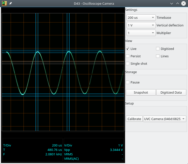
This is the software:
The camera looks like this:
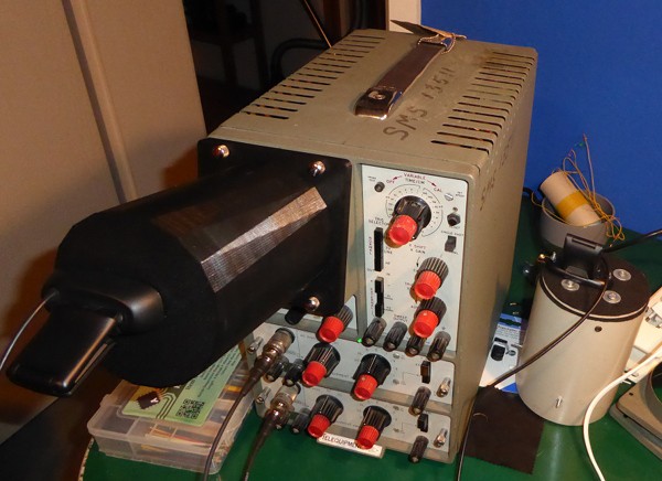
Beside the oscilloscope is the original prototype camera made of a section of 120mm diameter sewer pipe.
You may notice that the software doesn't have a typical menu structure, and that it doesn't try to match the appearance of the physical controls.
I learned a long time ago that on-screen replicas of mechanical switches are an absolute pain to control with a mouse and that they are wasteful of on-screen "real estate." My first experience with such things was using LabView on a monitor with a resolution of 640x480 - any wasted pixel was a serious loss in those days.
I'm also not a fan of digging through menus to control my equipment. I've used modern DSOs, and it always cheesed me off to have to wade through multiple menu layers to get to whatever setting I needed to change. I made the controls as simple as possible.
The "D" in "D43" is for "dual." The D43 has dual traces. The software has only a single set of cursors. Two sets is too cluttered. You can only make measurements on one trace at a time.
Behind the scenes, I use NumPy to manipulate the images. Python is an interpreted language, and by itself would be too slow to trim and scale the captured images in real time.
Yes, real time.
The camera is more or less permanently attached to the scope, and I use the software for all viewing.
The current camera is attached to the scope in place of the original hood. It can be removed just as easily as the original hood, but that's too cumbersome to be doing all the time. I just use the software at all times.
Since I already had NumPy in the software, I went ahead and used it to digitize the trace.
You can view the digitized trace only like in this picture:

You can also export the digitized trace as a CSV file. I've used it to import measurements into Baudline to do a spectrum analysis.
Here's Baudline analyzing a signal from the D43:

Yes, that's 10Hz. I was testing the persistence function, and digitized a very slow signal. Digitizing works just as well at the fastest sweep speed as it does at the slowest.
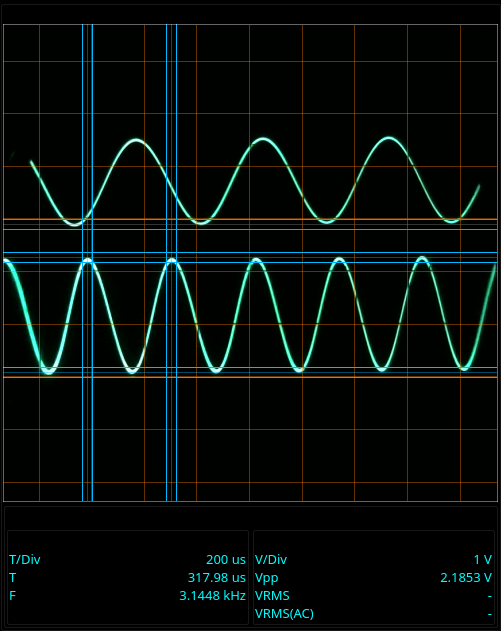
Digitizing cannot handle both traces at once, though. That's one of those cases where simple is really easy, and the next step up is insanely more difficult. The regular display and camera functions of course have no trouble with the dual traces:
The software cannot read the control settings from the scope. The switches in the scope controls are wired as part of the oscillator circuit (time base) or the amplifier (vertical deflection) - there is simply no reasonable way to tap into them to control the software. You must manually set the on-screen controls to match the settings on the scope.
You may have noticed that the entire CRT is enclosed. With the display enclosed, there are no reflections to obscure the image. In normal use, I turn off the backlight for the scope grid. The software generates its own grid. Turning off the backlight helps with reducing glare so that I can get really clean images.
I made the whole thing to work with my old D43, but nothing in it is really specific to that oscilloscope (except the camera mount.) You can use it with pretty much any scope and any webcam.
In case anyone really does have a D43, the drawings for the 3D camera are available in the repository along with the drawings I made for the prototype sewer pipe version.
I have a wiki setup on the GitHub page that explains how to install, setup, and use the software.
There isn't (as yet) an installer for the program. The wiki describes how to install the needed components and get the program started. If you'd like an installer, let me know and I'll see about making one.