 Noeël Moeskops
Registers
After looking at the data sheet for the registers it turned out that the device is pretty simple. At startup the IC is in low power mode, after setting it to normal operation mode the PWM of each pin can be set.
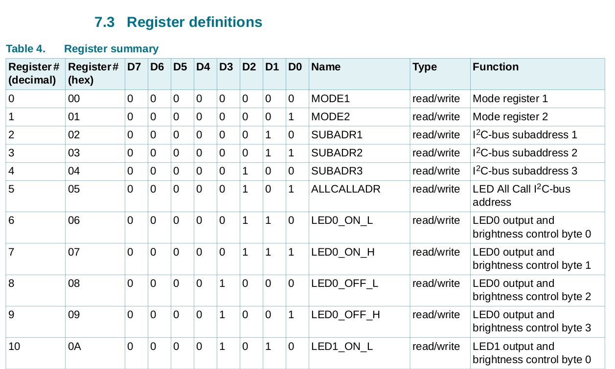
The register MODE1 contains settings to restart the IC, use external clock, power mode and set broadcast mode. MODE2 is less significant and contain some specific settings for I²C communication and PWM configuration, like putting the output pins to open-drain or totem pole(?). On address 0x6 the PWM output starts. (called LED because this IC is designed for driver LEDs, motors will also work fine).
So when writing to register 0x6 the PWM can be set by first specifying the time when the PWM needs to be turned on (0-2048, because register *_L and *_H are together 12bits) and then the time when the PWM needs to be turned off. The time is specified between one clock cycle. The clock of the outputs needs to be set separately and is the same for all the outputs.
Driver
Since PWM is such a common peripheral I created an abstract driver in the `aruna::driver::PCA9865` namespace.
// include/aruna/control/PCA9685.h

/**
 * Set the PWM of an output of the PCA9685
 * @param led, 0-15 output to adjust
 * @param on, 12bit time to turn on
 * @param off, 12bit time to turn off
 * @param address, I²C address of device, default 0b1000000
 * @return
 */
err_t set_pwm(uint8_t led, uint16_t on, uint16_t off, uint8_t address = default_address);
This is currently the only function that I wrote yet, very minimal. I want to create a working model as quickly as possible. Its actually only a header. Its Upton each platform to write an implementation for it. The ESP-32 implementation is found at `./src/driver/PCA9685/portable/ESP32/PCA9685_ESP32.cpp`.
To enable this driver to work seamlessly in place of my previous PWM driver (that uses the GPIO pins on the ESP) I had to create a wrapper of sorts for the `Control::Actuator` class. `Control::Actuator` Is a virtual class so that the control module have a common interface to control actuators on the ROV. Multiple actuators of different natures can be used at the same time.
// include/aruna/control/Actuator.h

/**
 * Set the speed of the motors directly
 * @param axisMask, multiple axis to apply speed to.
 * @param speed, speed of the motors
 * @param direction, direction to go to.
 * @return err_t::OK if the command was succesfull, others when it fails.
 */
virtual err_t set(axis_mask_t axisMask, uint16_t speed, direction_t direction) = 0;
The `set(...)` function is the only required function of an `control::Actuator` class driver implementation. `axis_mask_t` specifies the axis that needed to be driven (X, Y, Z, Roll, Pitch and Yaw). If a given driver can't perform a given axis transformation it wil just return.
This layered driver structure allows me to quickly switch between hardware.
// include/aruna/control/PCA9685.h

/**
 * PCA9685 I²C PWM driver
 * @param axis: supported axis masks
 * @param direction: supported directions
 * @param led: PCA9685 LED output number (0-15)
 * @param i2c_address: address of the PCA (default 0b1000000)
 * @param min_duty_cycle_percentage: minimal duty on percentage (default 0)
 * @param max_duty_cycle_percentage: maxumal duty on percentage (default 100)
 */
PCA9685(axis_mask_t axis, direction_t direction, uint8_t led, uint8_t i2c_address, float min_duty_cycle_percentage = 0, float max_duty_cycle_percentage = 100);
Above shows the constructor for the PCA9685 `Control::Actuator` driver. As required by the parent class it needs to be supplied with an axis mask and direction. Other parameters are specific for the PCA9685. Although I took a peek at the ESP32 native PWM driver that I have written earlier and copied `min/max_duty_cycle_percentage`. This is needed for the SimonK driver as it operated within 5-10% of the PWM signal.
Each actuator needs to be registered by the control module by executing `control::register_driver(...)`. Then (after the control module has been started with `control::start()`) all the actuators can be controlled simultaneously with `control::set_speed(...)`. The control module also features some more abstractions, cool features and manages the input from the surface but that's out of the scope of this blog.
// include/aruna/control.h

/**
 * register an accelerator driver for use.
 * @param driver pointer to the driver
 * @return `err_t::OK` if it went well.
 * `err_t::FAIL` if not.
 */
err_t register_driver(Actuator *driver);

/**
 * initialize control and communicate with hardware for active modes.
 * @return status_t, returns current status of the module
 *  * `RUNNING` if it is running,
 *  * `STOPPED` is it us currenty stopped.
 */
status_t start();

/**
 * Set the speed of the motors directly
 * @param axisMask, multiple axis to apply speed to.
 * @param speed, speed of the motors
 * @param direction, direction to go to.
 */
void set_speed(axis_mask_t axisMask, uint16_t speed, direction_t direction = direction_t::PLUS);
There is still some work to be done with this infrastructure, driver layout and especially the PCA9685 implementation as it is a bit rushed at the moment and it has not all the abstraction layers that I would like to see. (like the I²C abstraction that I talked about earlier).
In the next blog I will discuss the testing of the driver and the assembly of the ROV.
See the relevant Aruna git comment and Apsu git comment for more details.
Discussions
Become a Hackaday.io Member
Create an account to leave a comment. Already have an account? Log In.