Some years ago - never mind how long precisely - having little or no money in my purse, I had the water in our borehole tested, and found that it was good and eminently suitable for human consumption. Soon a reserve tank was mounted on a platform, with a booster pump beneath it, and some plumbing was perpetrated to facilitate switching between municipal and own water.
Four times a day an irrigation controller activates the borehole pump, and, while the garden is watered, the tank is also topped up via a float ball valve mounted at its inlet.
But, of course the tank is too small for when the unwashed masses want to, well, become the washed masses, which tends to happen all at once. A bigger tank might have helped, but due to the constrained purse mentioned above, as well as the limited space behind the trunk of the carob tree, a plan was devised to automatically switch on the borehole pump when water levels are low, and then of course off again when it has been filled up sufficiently.
With an aversion to drilling holes in the tank, and also not wanting to run wires into the water, as would be needed when using commercial water level switches (which I did not have anyway), I devised a setup using a magnet floating in a food-safe polyethylene bottle inside the tank (which is also made of polyethylene). The magnet is sensed using reed switches mounted on the outside of the tank, so that water and electricity do not have to mix. Two nonmagnetic stainless steel rods inside the tank form a track constraining the movement of the floating bottle to a vertical trajectory near the side of the tank.
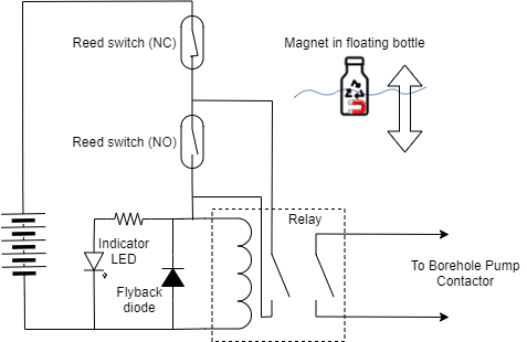
Diagram showing self-latching relay with two reed switches activated by magnet inside the tank
Near the bottom of the tank is mounted a normally-open reed switch, which closes when dropping water levels cause the magnet to approach it. When this happens a relay is energised, which self-latches using one of its sets of contacts. The second set of contacts is connected to the contactor controlling the borehole pump, which is therefore also switched on. Eventually water wends its weary way from the depths of the earth and into the tank, causing the water level to rise. Ultimately the magnet floats up, up and away from the bottom reed switch, causing it to open again. This does not matter, though, because of the self-latched relay, which stays on, keeping the borehole pump working, until the coil current is interrupted by the top (normally closed) reed switch, which opens when the magnet eventually rises to its level. A flyback diode across the relay protects the reed switch against the back EMF generated by the coil when the current is interrupted.
This setup is attractive, not only due to the magnet, but also because it contains no sensitive electronics which can be damaged by lightning-induced spikes – a very real issue owing to the approximately 20m of unshielded wire running outside between the reed switches and the rest of the circuit, which resides in the garage near the irrigation controller. There is also no internet connectivity hassles, security challenges, spyware, or incessantly updating software to contend with. Unsurprisingly, it has functioned perfectly from day 1. Only very occasionally do I remember to use a few litres of municipal water, just to keep the meter ticking over. They have already come to replace the meter once, no doubt theorising that it was broken because it registers almost nothing per month.
Now for the fun part: Despite there being no need, there was still a desire to know the actual water level in the tank, in a similarly robust and hassle-free way. It is important to remember that everything one installs has to be maintained, so it behooves one to be circumspect regarding the future support burden that comes with every device built or acquired. Keep it simple, in other words. For a brief moment I considered mounting a manometer-style tube on the outside of the tank, with the water level in the tube following that inside the tank. One could even float a brightly-coloured ball in it, to make the level clearly visible. However, because the tube has to be clear, to see the water level, the concomitant exposure to light would soon lead to algae growth, which is a consummation devoutly to be avoided when dealing with supposedly potable water, in addition to the fact that such growth will eventually obscure the indication itself. Other approaches that were considered involved a float inside the tank, linked by string and pulley to some indicator on the outside - but it lacks elegance, and I still was loath to drill holes in the tank, so this idea was discarded too.
However - we already had a moving magnet at the water level; all that was needed was something to sense its position. That something turned out to be a 32mm steel washer, pivoting on an axle. How do we fix an axle to a washer, you ask? (You don’t? Well, you should.) We spotweld it, of course, using a 3D-printed jig to ensure the thin wire axle is properly centered. Before this could be done the washer was trimmed to a width of 25mm, because the plan was to fit it into a 38mm OD glass tube, and we needed some space for the uprights. Uprights? What uprights? More stainless steel rods, but do not despair - all will become clear soon.
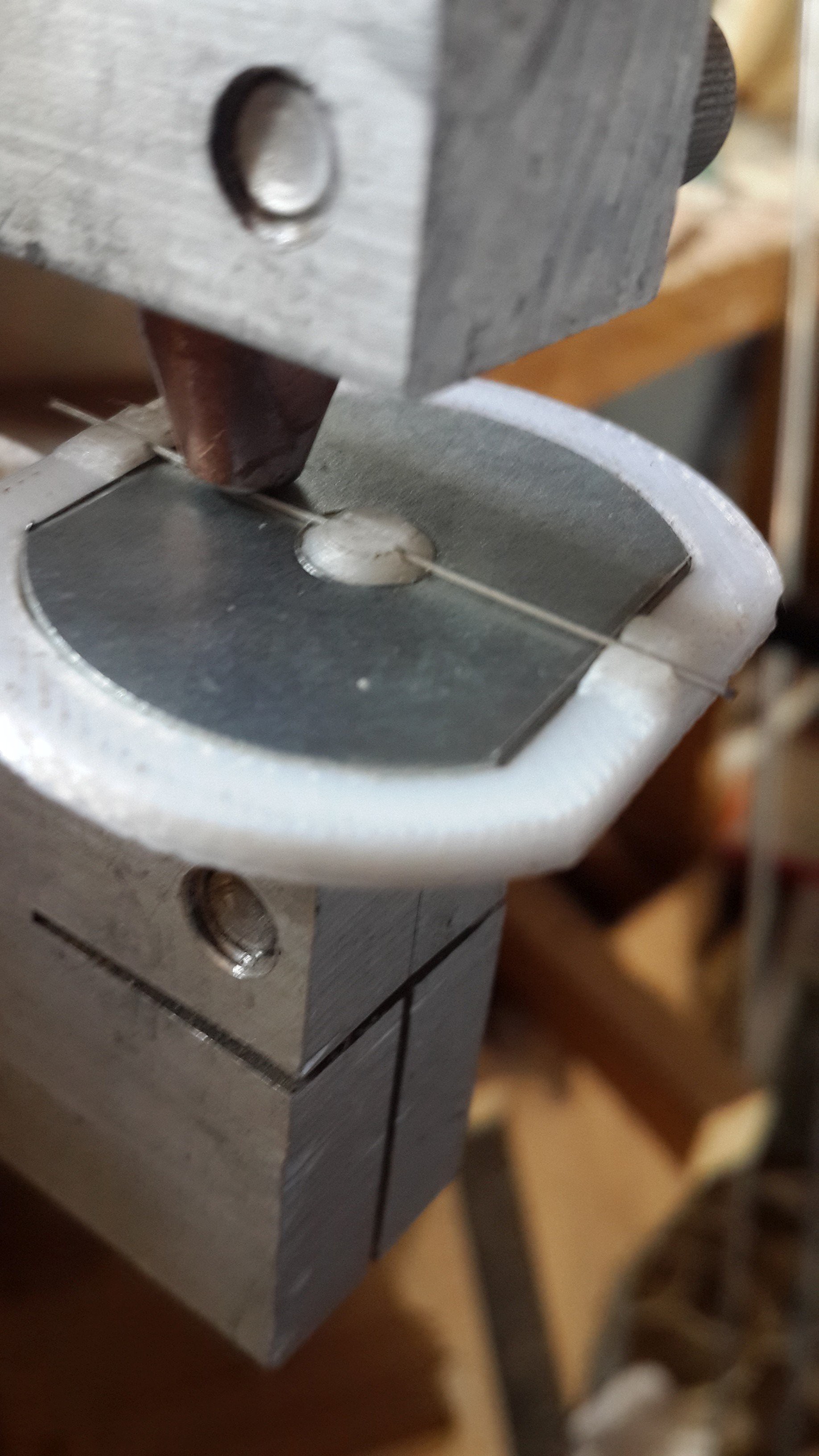
Steel washer in jig, having an axle welded to it using the obligatory homebuilt spotwelder
With the envisaged spacing we needed 23 pixels. So we rinsed and repeated.
Before mounting, the discs had to be painted in contrasting colours: black on the one side, and high-visibility yellowish-green on the other.
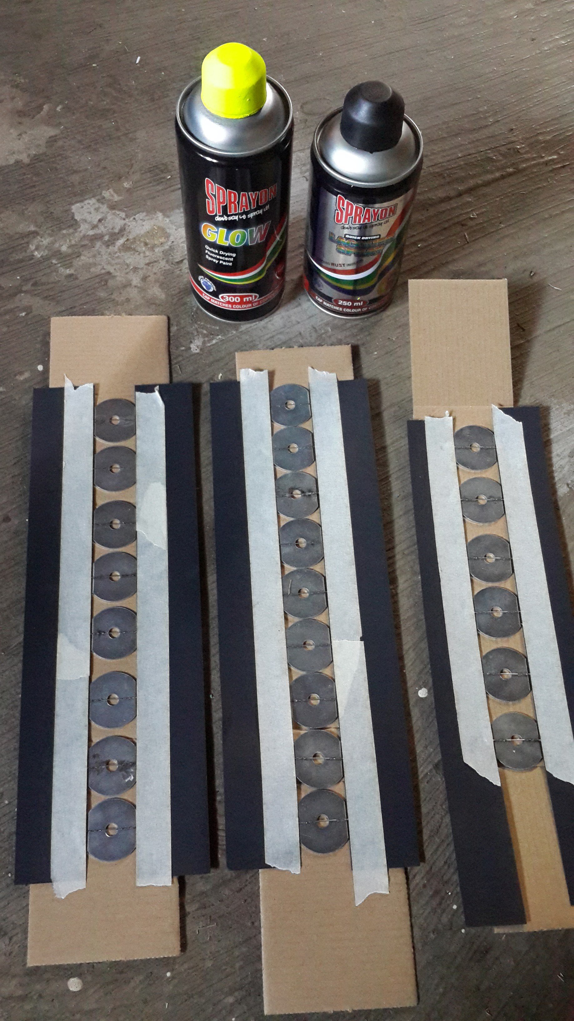
The axles were masked off before painting, to keep them clean and smooth
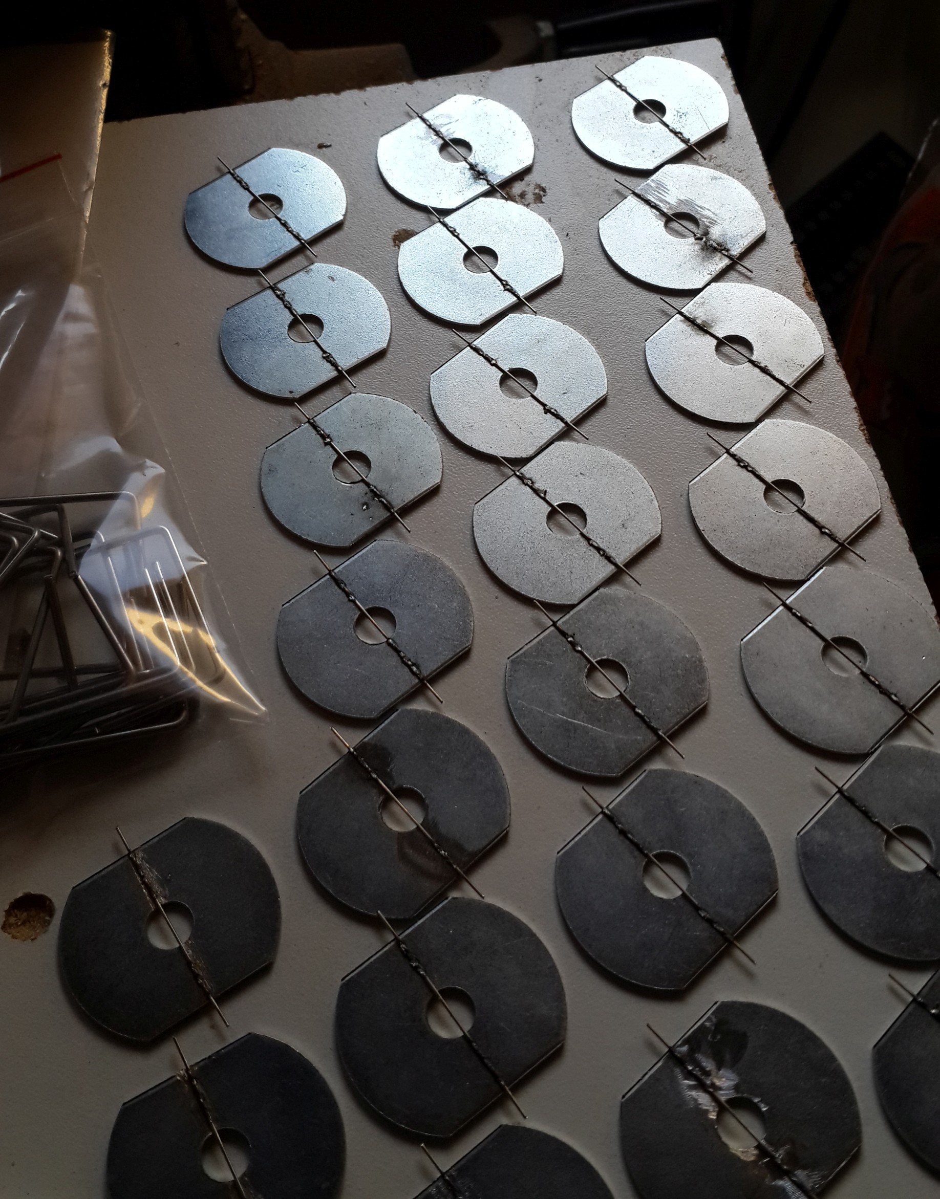
Stainless steel rods for the uprights, steel washers before axle welding, U-shaped crosspieces and mounting jigs used during spotwelding
The axles of the washers fit into slots in the uprights, made using a hacksaw. A U-shaped crosspiece is then spotwelded over these slots, to capture the axles, and also to function as an endstop for the washer, when it is flipped over by the magnet.
To ensure even spacing, another jig was designed and printed. This one helps to maintain the distance between the uprights, guide the hacksaw when sawing the slots for the axles, and to space and position the crosspieces when they are spotwelded in place.
Close-up of some mounted pixels, showing both sides, as well as 3D-printed spacer rings clipping onto the crosspieces.
The horizontal part of the crosspieces stop the pixels from turning all the way around, while the two vertical arms (by which it is spotwelded to the uprights) also pass over the slots sawn into the uprights for the pixel axles.
More 3D printing resulted in end caps for the glass tube (to keep out wind, rain, dust, insects, and arachnids), as well as spacing rings which clip onto every second crosspiece. These spacers help to maintain everything nicely centered in the tube, ensuring there is sufficient space for the pixels to flip over. Now at last you can see why we had to trim the widths of the washers. Luckily there is a guillotine in the workshop at work, which made short shrift of the steel.
So – how does it work? With the uprights, well, upright, the axles are horizontal, and the washers (pixels) settle into a vertical orientation, stopped by the crosspiece at the bottom. At this stage either colour can be facing forward. They are stable in either position (hence the ‘passive’ qualification) because the axle is fixed to the side of the washer, causing it to overbalance when it passes the horizontal. When a passing magnet tugs at the steel washer, it can only lift the bottom edge of the washer if that happens to be on the magnet side of the crosspiece, which should be the case if the magnet approaches from below. (If not, it will be on the next iteration, and thenceforth.) The pixel starts to swivel, following the magnet as it moves, until the magnet is so far away that the pixel passes from its thrall. By that stage it is well past horizontal, so it settles against the crosspiece with the other colour facing forward. When the magnet now moves down, the opposite happens, resulting in a bar-graph type display showing the position of the magnet, and hence the water level.
A picture paints a thousand words, and a video even more, so here goes:
Timelapse (60x speedup) showing the tank emptying, and then being filled again behind the trunk of the carob tree.
No software, no wifi or internet, no Arduino or 555, and not even electricity needed for the display, which is clearly visible from afar (even at night, because of the security light above the garage door , which, admittedly, does use electricity. The light, not the door.) Do note that there is a firm plan to NOT aim a webcam at it, not processing out the position, and most certainly not internet-of-thinging any of this, due to the intolerable maintenance burden that this would bring. It would also be inelegant, which is worse.