 Leonardo Ward
We are currently working on new designs for the Intelligent Buoy and the Onboard Gateway, in those designs we will replace the previous development boards for our own implementations, and that includes the ESP32-DEVKITC-32D.
The design can be found in the following Github repository.
We want to replace the ESP32-DEVKITC-32D with the ESP32-WROOM-32D and include it directly in our new PCB. To achieve that goal we have developed the following circuits:
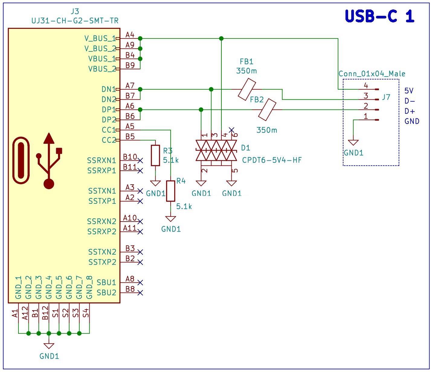
USB C Port and Electromagnetic Compatibility (EMC)
Everything starts with the USB C port, we have chosen this type of USB because it's size and because of the growing trend of using this port to charge and communicate with portable devices.
We have included Transient Voltage Suppression (TVS) diodes and Ferrite Beads to reduce the Electromagnetic Interference (EMI). These protections for the USB port will add compliance with the EMC regulations and standards from the Federal Communications Commission (FCC) and the European Union.
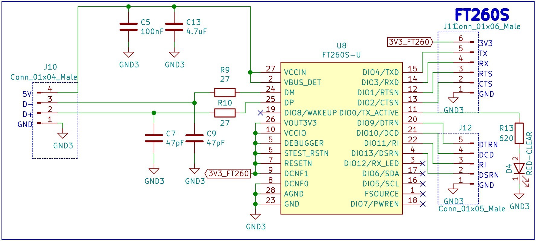
FTDI 1: FT260S-U
The first USB TO UART/I2C FTDI that we want to test is the FT260S-U. In the design we are only considering the USB to UART, therefore the I2C is left unconnected.
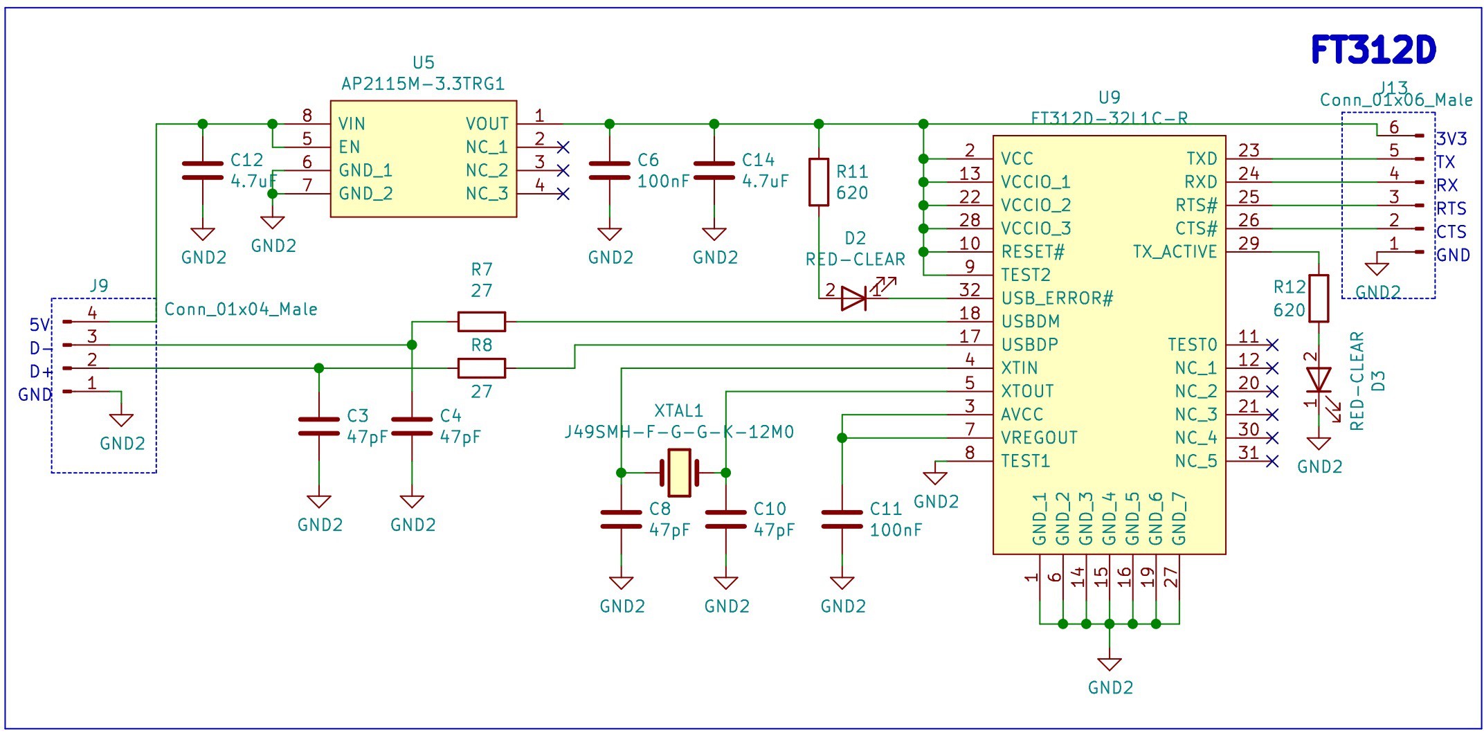
FTDI 2: FT312D-32L1C-R
The second USB TO UART/I2C FTDI that we want to test is the FT312D-32L1C-R. This IC does not support DTR/DSR for the UART, a feature that we require for the auto reset circuit of the ESP32, nevertheless we decided try it as a second alternative.
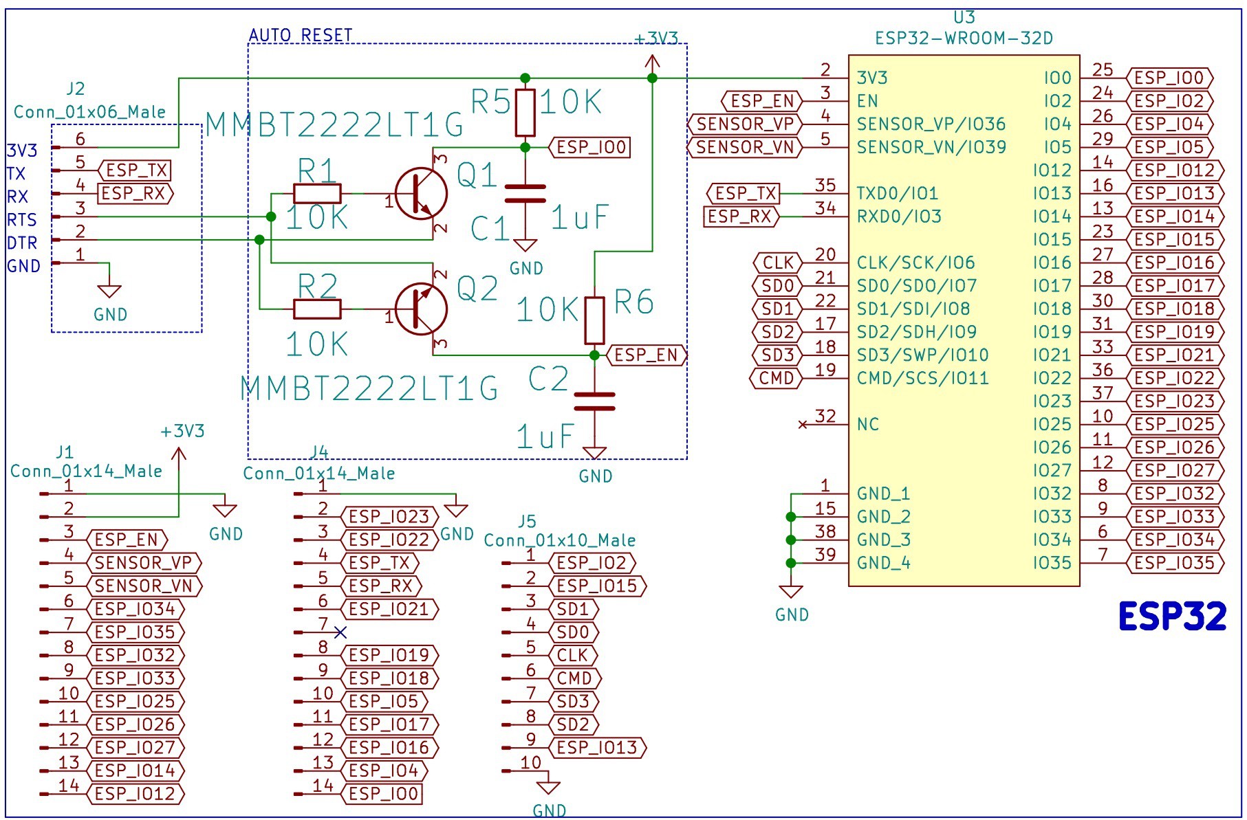
ESP32 with Auto Reset
Finally, we have the ESP32. We have included an auto reset circuit that uses RTS and DTR to reset and put in bootloader mode the ESP32. For more information about this circuit, these blogs [1] [2] can be useful.
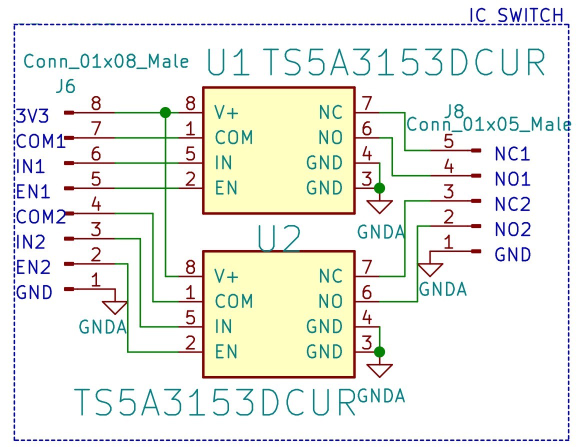
SPDT Switch
In this design we also included a couple of TS5A3153DCUR that we want to test for future implementations.
Bill of Materials
PCB


Discussions
Become a Hackaday.io Member
Create an account to leave a comment. Already have an account? Log In.
Amazing Leo!!!! Congratulations!!
Are you sure? yes | no
Thank you!
Are you sure? yes | no