 lion mclionhead
The official compact flashes like the EL-100, 430EX, 270EX are insanely expensive. Lions are manely interested in something portable for fill light but for some reason, most of the cheap flashes are giant ones with fully articulated heads. Cheap flashes in a compact size are hard to find. Quality apparently suffers, even at $30.
https://www.amazon.com/SFD450C-Digital-Dedicated-Autofocus-Illuminator/dp/B008CPQ1O4
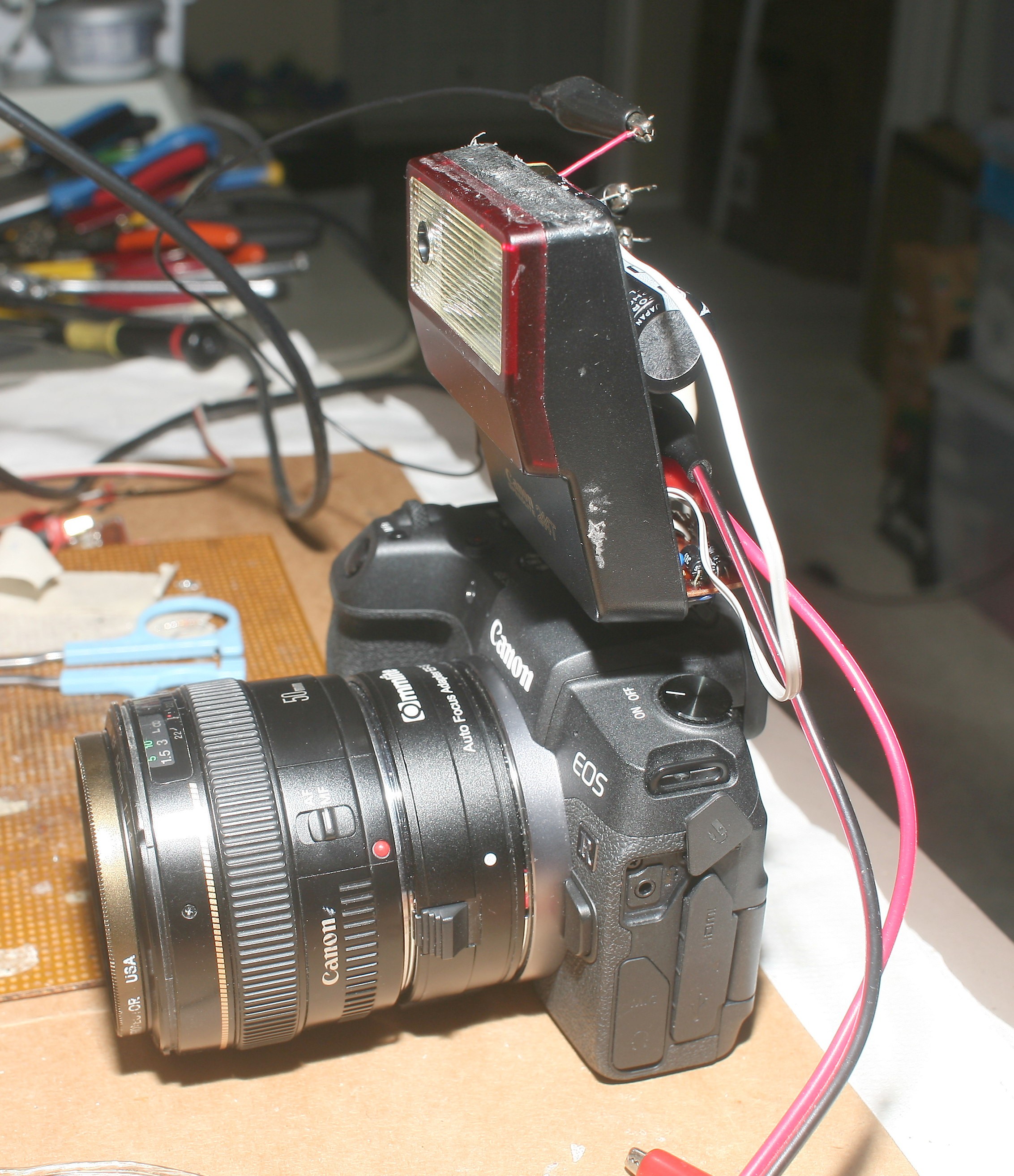
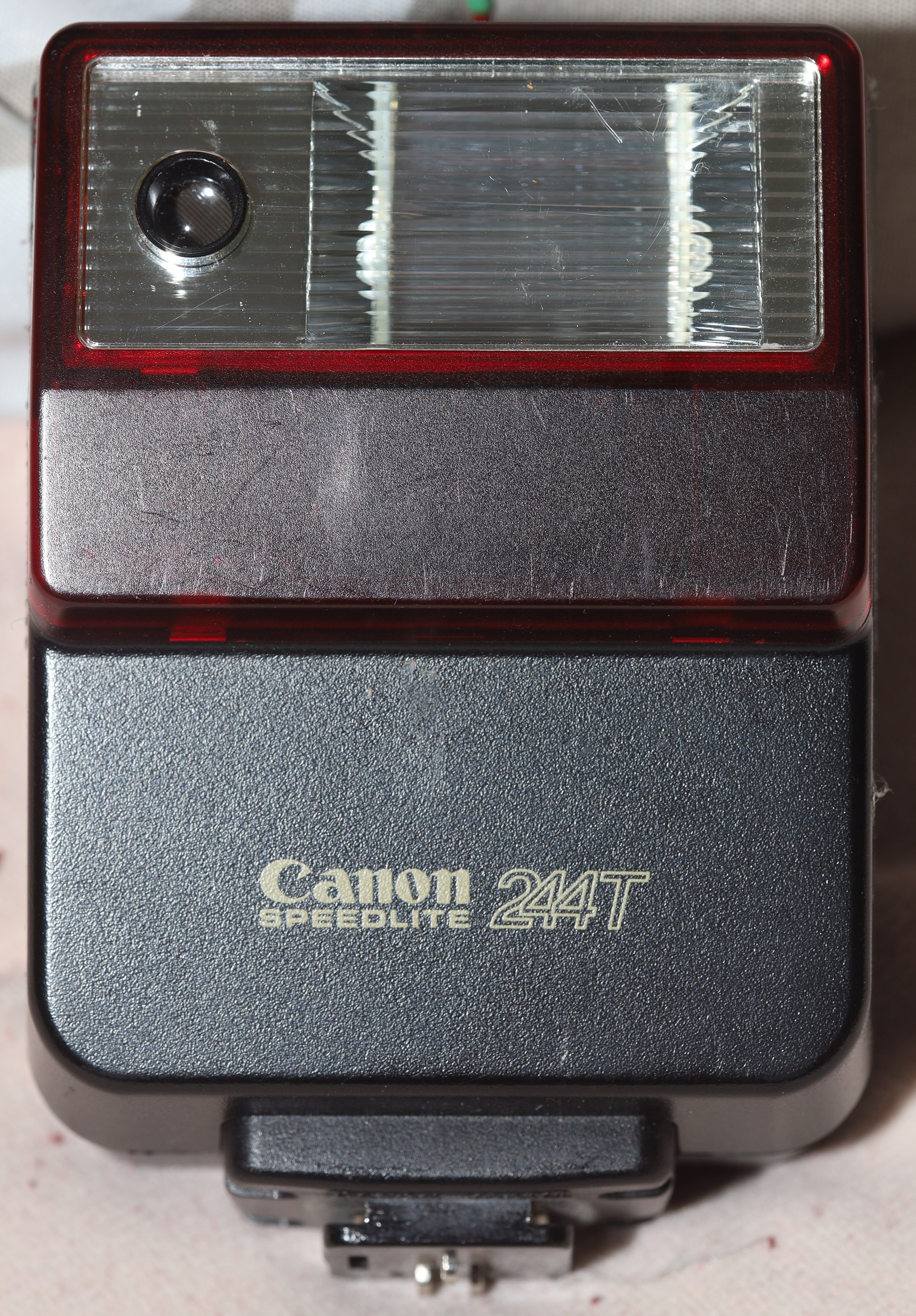
The mane problem with the 40 year old flash is lack of TTL. It has variable power, but is locked into a very poor auto exposure system that might have been optimized to just work with the AE-1 Program. On any modern camera, the 244T's auto exposure doesn't produce useful results. Any kind of auto exposure was essential 40 years ago when every photo cost money. Nowadays, you can take test photos & dial in manual power settings. The original flash is completely useless, by modern standards. To make it minimally useful, it just needs a manual override.
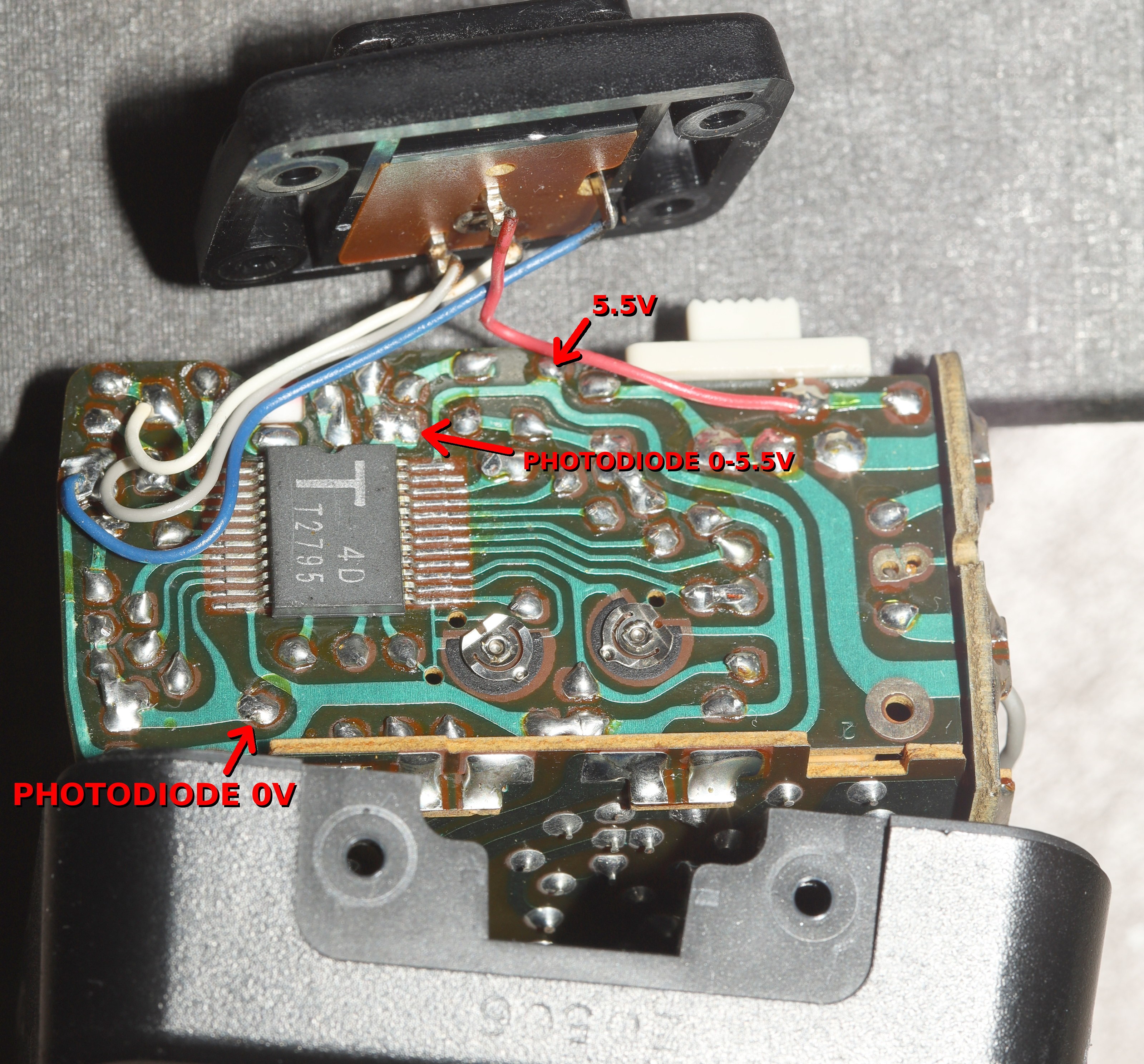
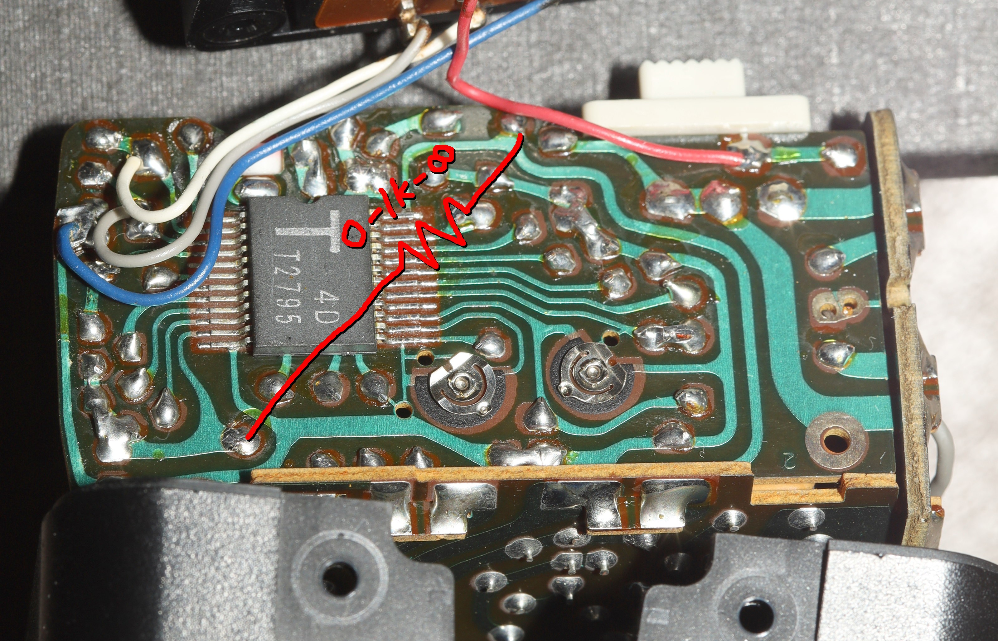
The 244T has a phototransistor which turns on in bright light. There's no amplifier. It connects directly to a microcontroller. The brighter the scene, the more it pulls down a 10k resistor. A mechanical filter for lowering the ISO decreases its amount of pulldown by around 0.1V.
The microcontroller sees 0V in the brightest light & 5.5V in the darkest light, with the mechanical filter increasing the voltage by 0.1V to simulate a lower ISO.
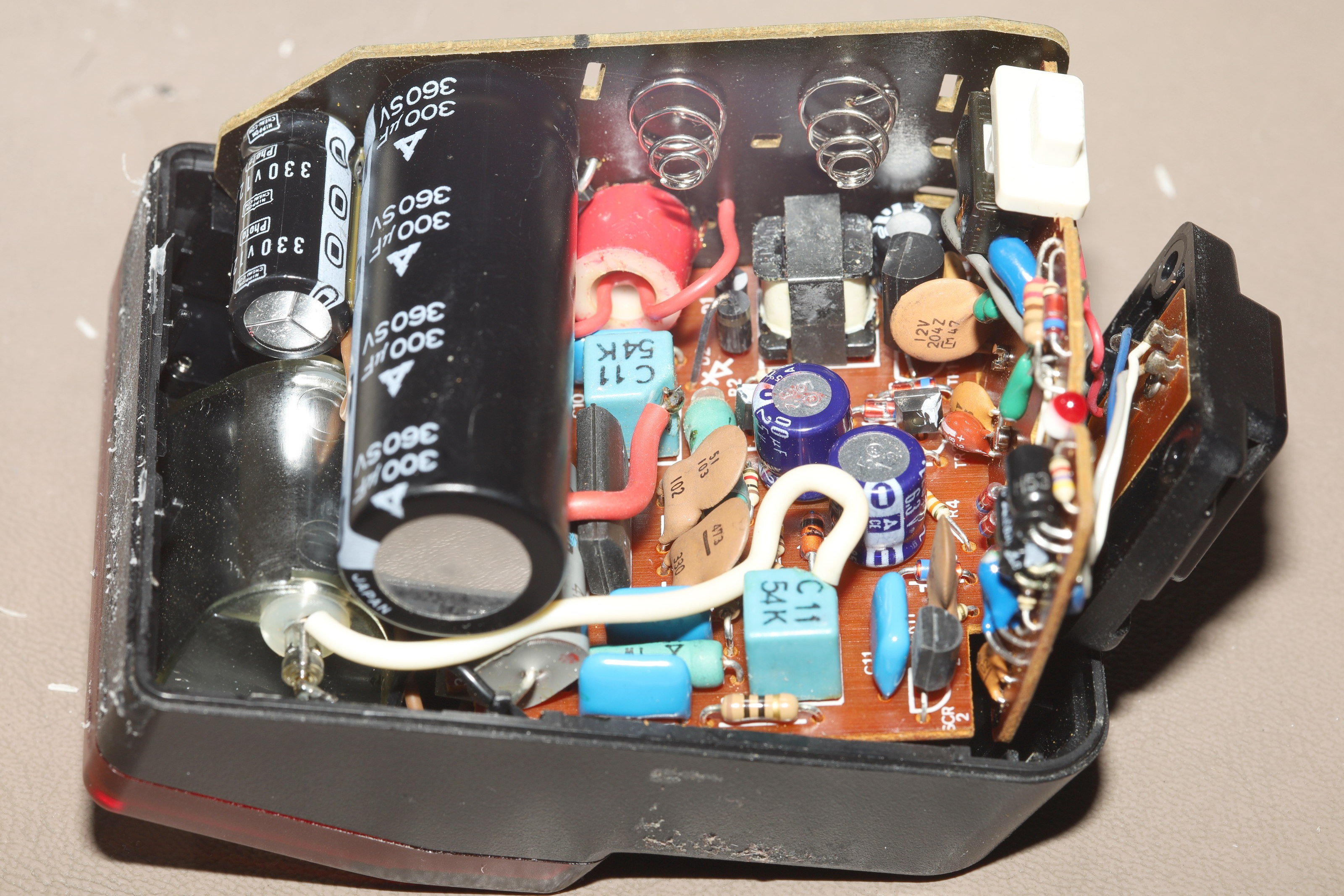
The 80's electronics smell is unleashed. The caps store 313V.
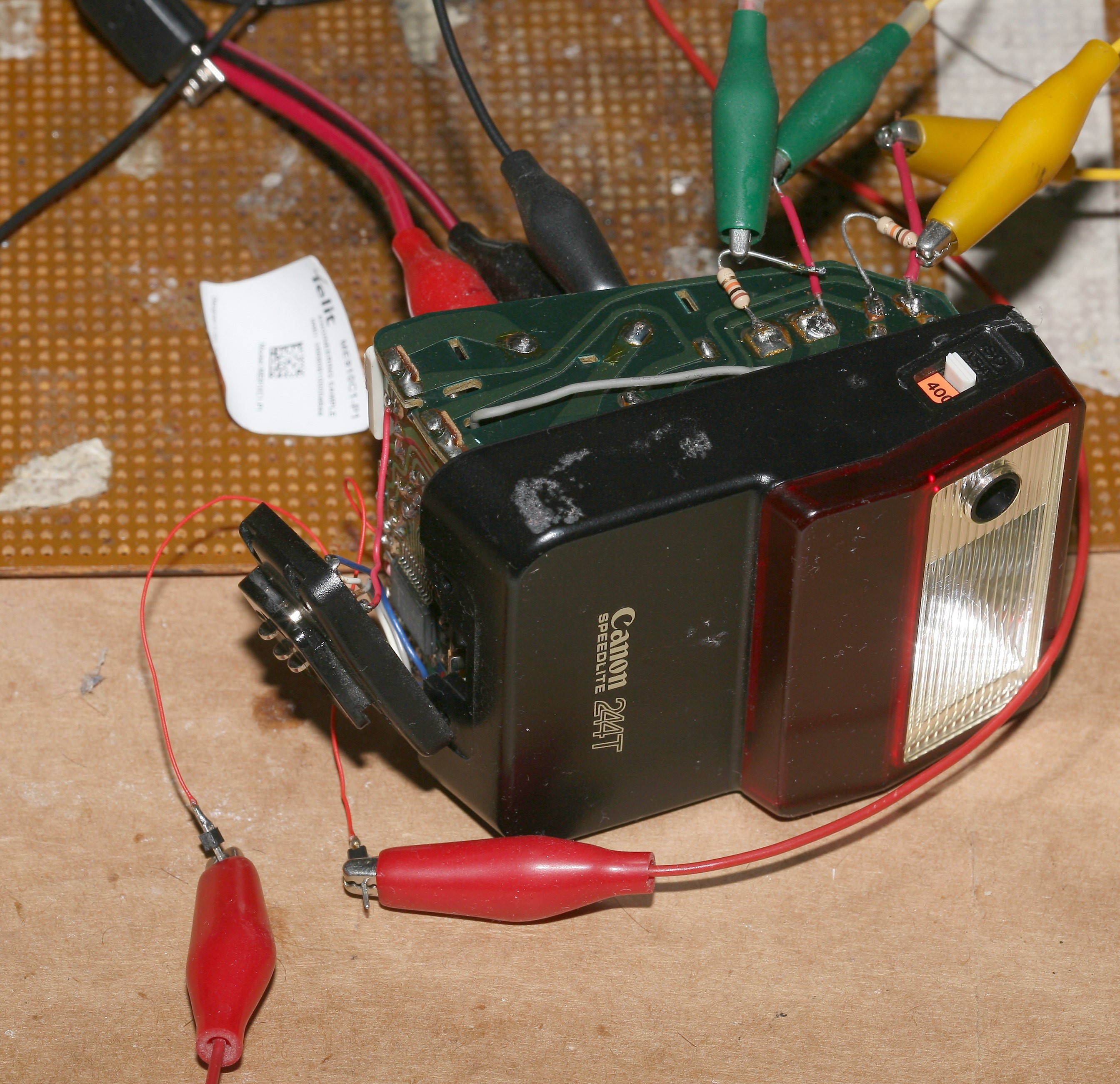
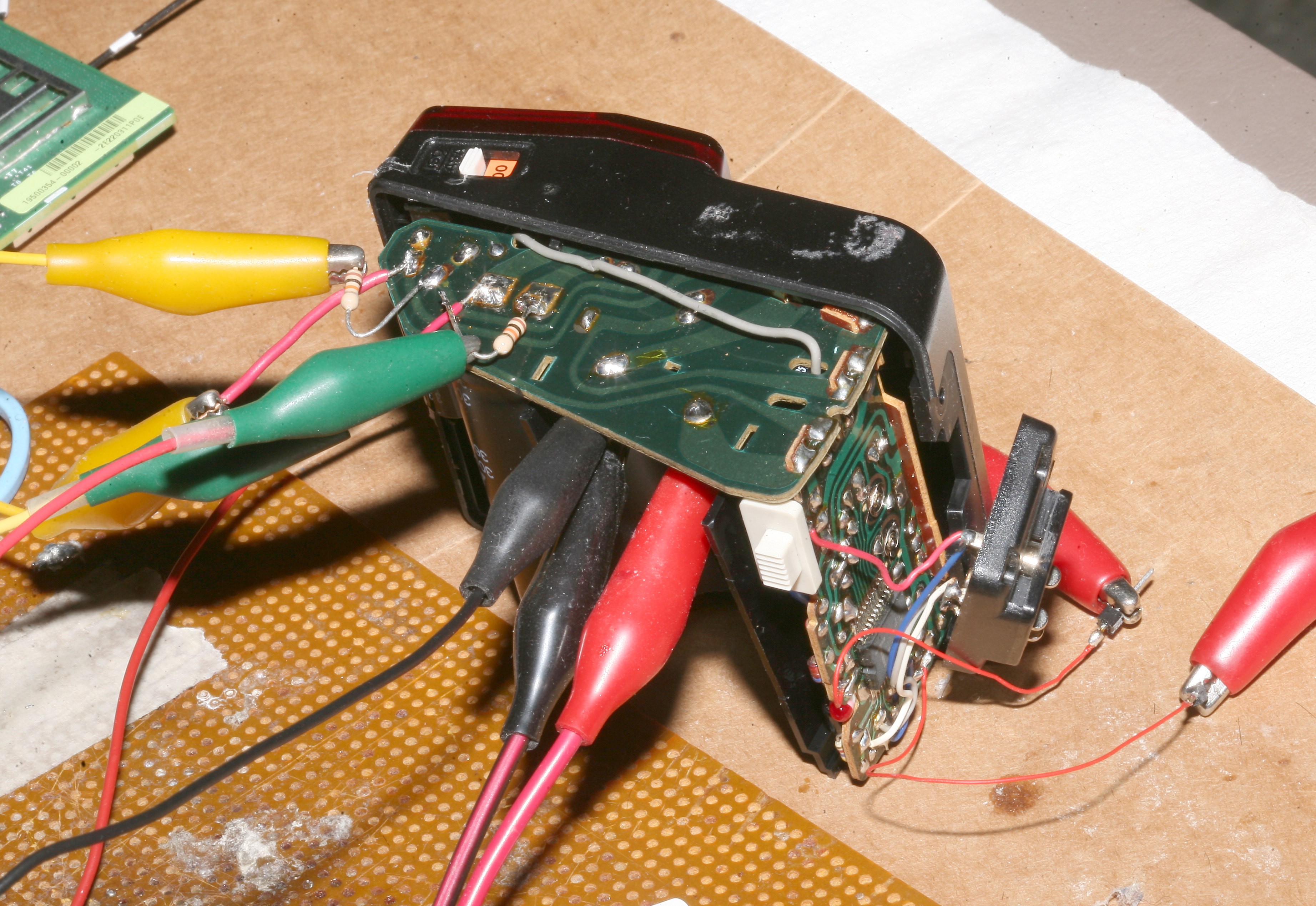
How to probe around 313V. Note the use of jumper cables & 10k resistors to drain the caps.
The early 80's LED was fascinating. They were yet to standardize even the lowly red LED's package.
It should have been a matter of replacing the phototransistor with a pot to adjust brightness, but instead, the flash was now at full power for all voltages. A terrible tragedy indeed.
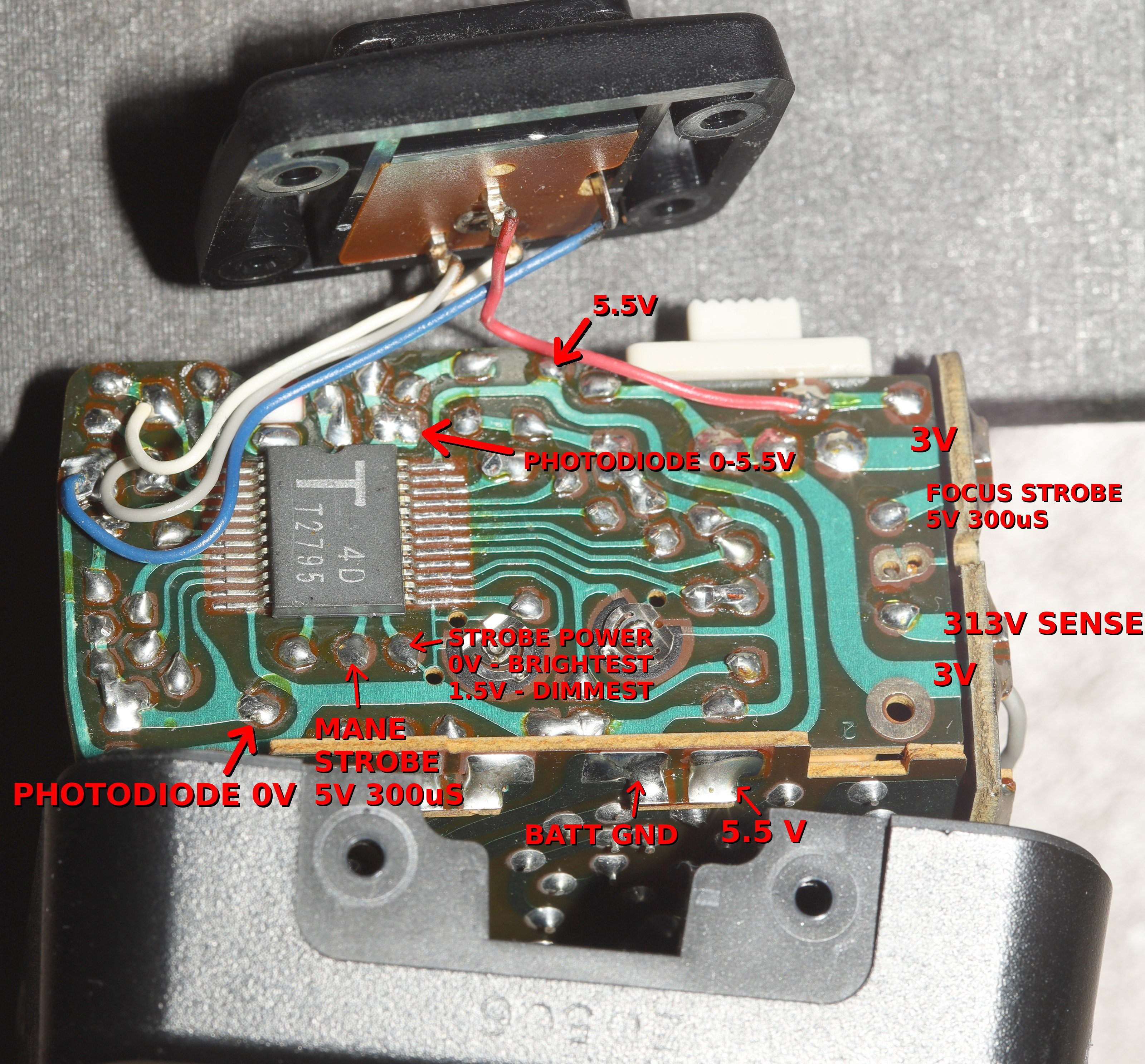
Some more probing revealed the phototransistor is required to get variable output. It's either providing active feedback during firing or the flash requires a certain amount of current into "photodiode 0V". Providing the right voltage to "photodiode 0-5.5V" isn't enough. The voltage divider would need to be the right resistance to guarantee photodiode 0V was also the right voltage.
Some more pins were revealed. It has a 313V pin next to the brain. No concept of a high voltage side & a low voltage side in those days. It has 2 pins to drive the focus & the mane strobes independently. LEDs weren't bright enough to serve as focus illuminators in those days, so it has a completely separate high voltage flash for it.
1 pin sends out 0V DC to cause the brightest flash & 1.5V DC to cause the dimmest flash, but it doesn't change during firing as would be required if active feedback was being used. The strobe duration doesn't change based on brightness, either. It's always 250uS. Holding the 1.5V pin at 1.5V causes the capacitors to drain without flashing. It has to be pulsed with the flash.
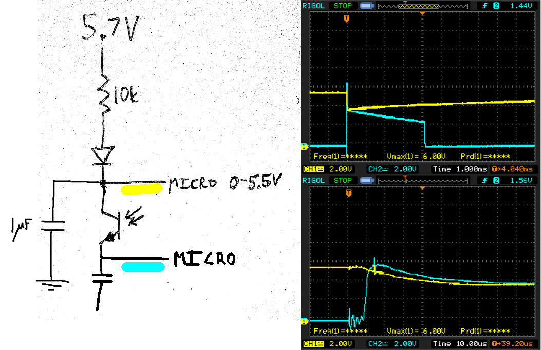
Another probing of the photodiode circuit showed it does create transients during the flash. There's a very long 1/250 pulse in the low side, seemingly activated by the micro. There's a drop in the high side from the light reflecting back to the transistor. The micro uses the amount of transient drop during the flash to determine how long to flash but no signal was ever implicated in controlling the strobe length.
Even with the electronics of 1984, flash exposure algorithms had grown into quite complicated beasts just to get the limited results they gave. Given the complexity of the purely electronic solution, the next idea was just shining an LED into the phototransistor to control brightness.
Shining an IR LED into the phototransistor provides some manual control. With the LED off & the yellow line above 2V, the flash emits low power. With the LED on & the yellow line below 2V, the flash emits high power. The threshold between low & high power is around 2V on the yellow line. There's no other power level.
This is the opposite behavior than observed with the photodiode completely taped over, because light leaks in, but it finally allowed selecting 2 power levels & the relevance of the blue voltage.
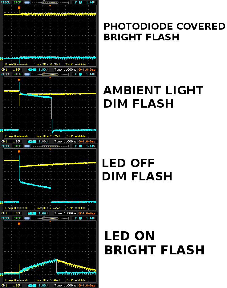
It finally turned out the blue voltage was directly controlling the flash power with no transients required. Set it to 0V to get maximum flash power. Set it to 2.5V to get minimum flash power. Helas, experiments feeding fixed voltages into the blue voltage gave erratic results.
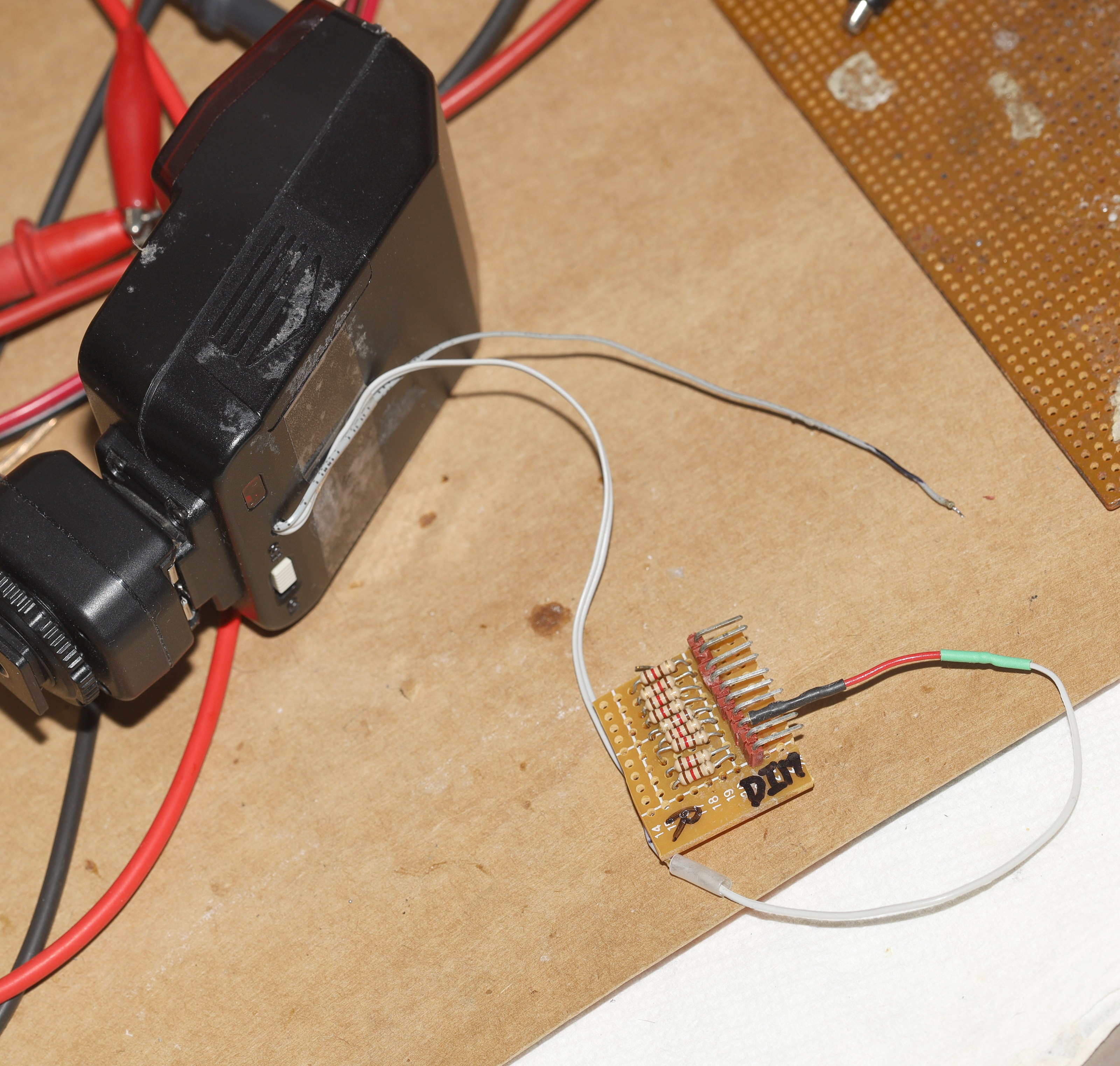
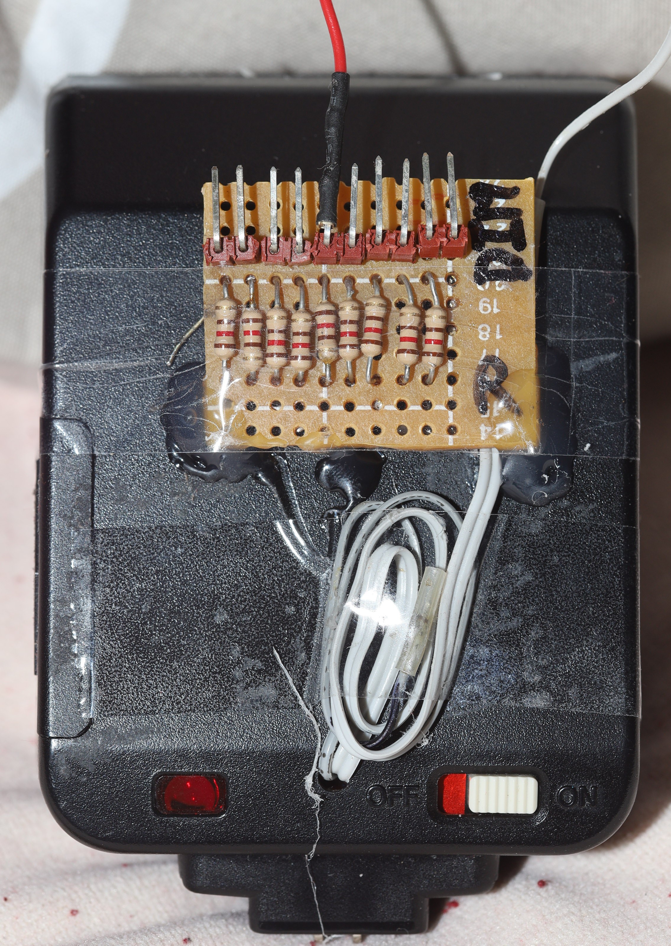
In the end, the way to control power was determined to be resistance between 5V & photodiode 0V. The lion kingdom improvised a control out of 120R resistors & a jumper. It would have been a lot easier with a 1k pot, but it's not like there's a store within 10000 miles which sells 1k pots.
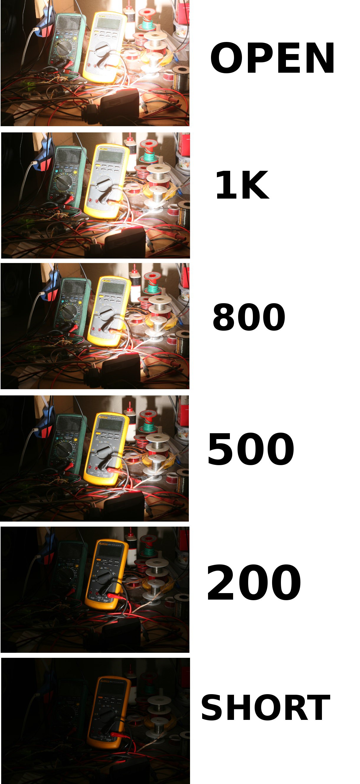
It was surprising just how repeatable the control was. Most of the variation was between 0 & 1k. Open circuit gave the brightest. The lack of such a simple control showed how they never envisioned anything beyond the film world.


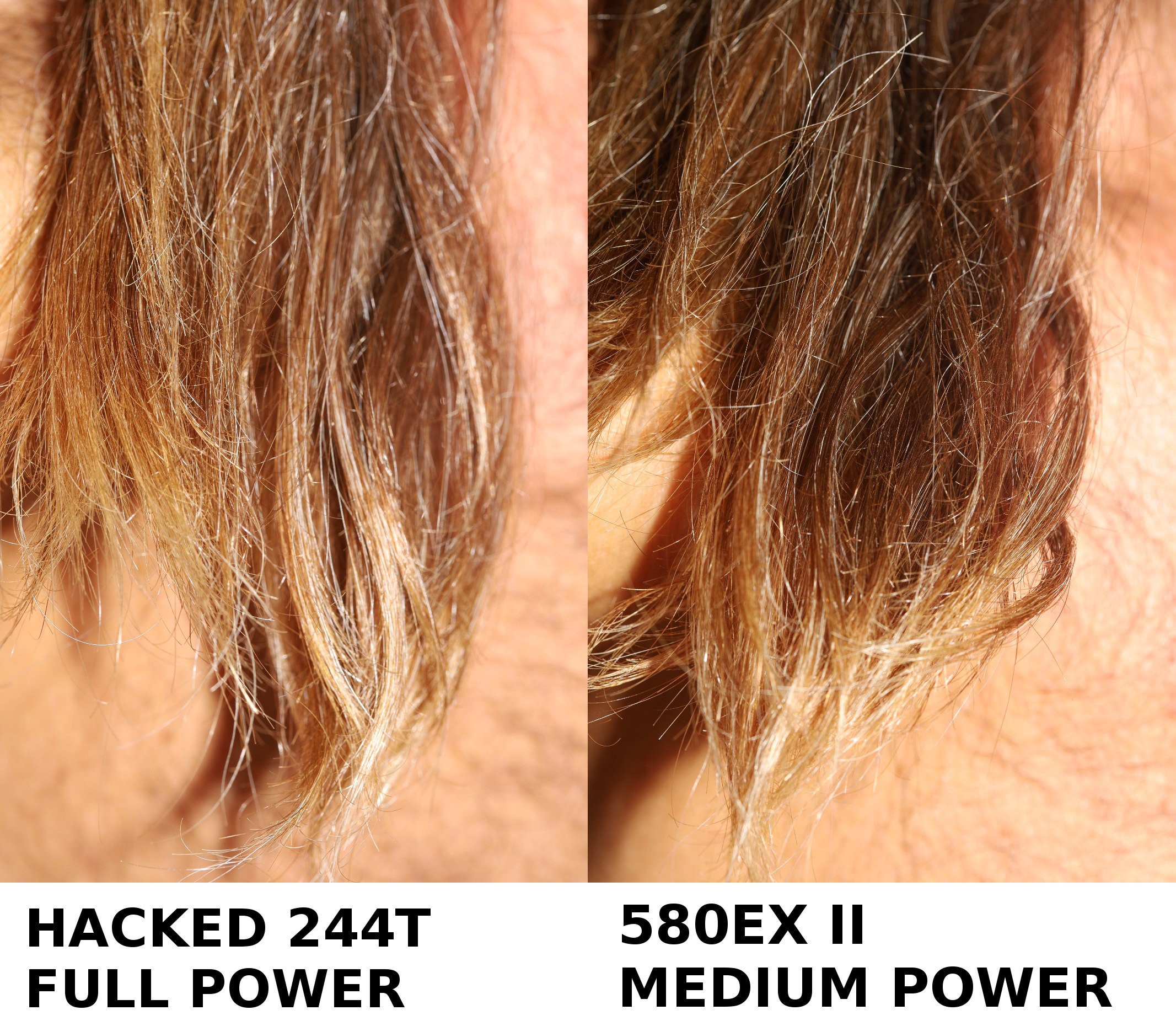
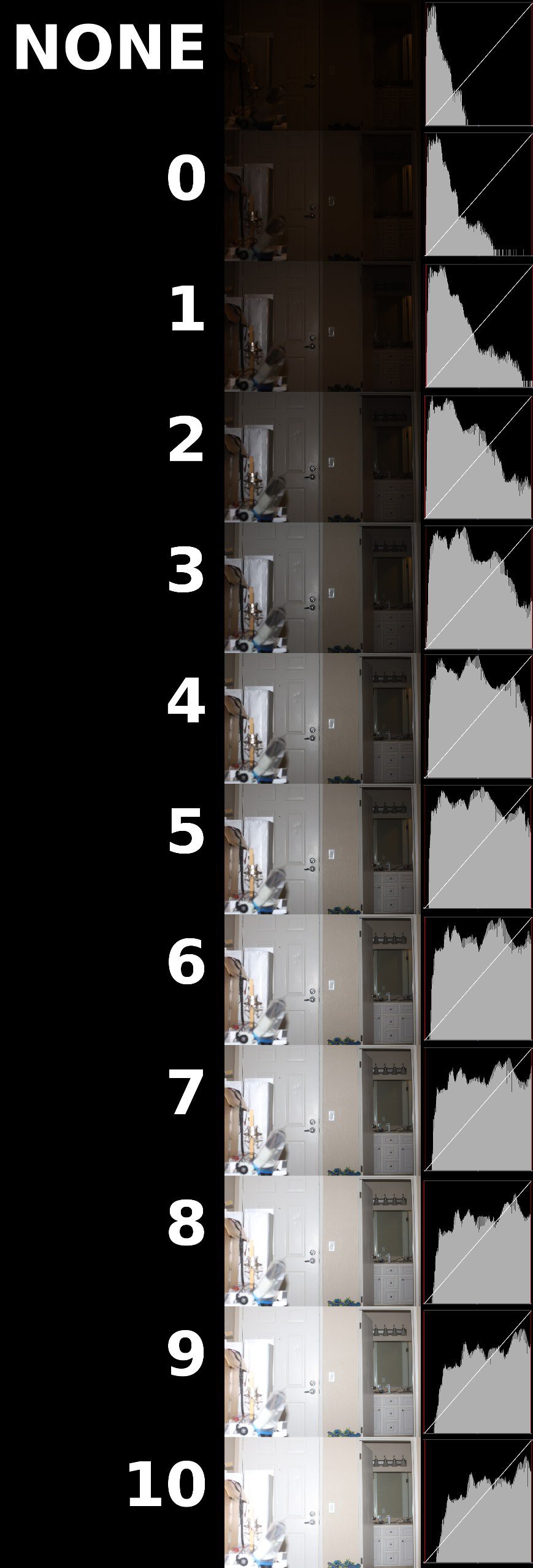
With manual exposure achieved, lions started wondering how hard it would be to put in TTL support. It would involve firing upon a command & adjusting power upon a command. It would be a lot of work for diminishing returns. In test shots, it always had to be fired at full power. In the worst case, it could require 6 power levels & take 3 test shots to get the right power. The 10 power levels were definitely overkill.
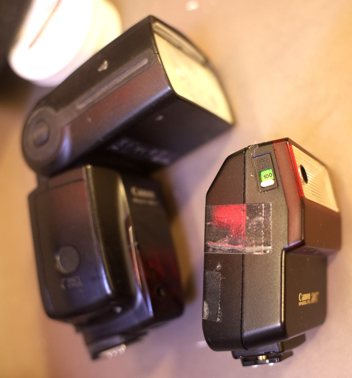
Let's compare the 244T with the war horse 580 EX II.
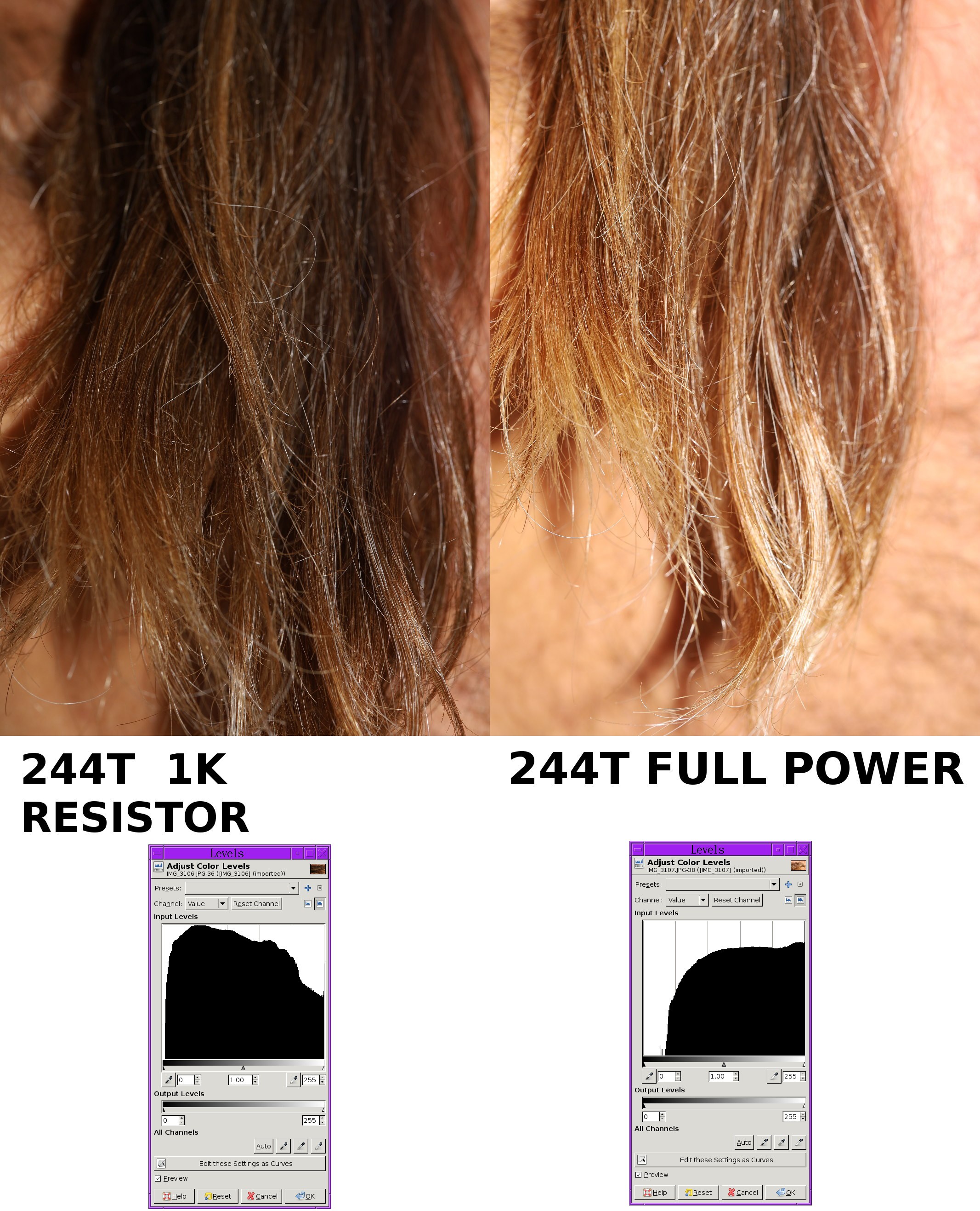
The 244T could definitely use more granularity at high powers. It could be done with a 2nd coarse adjustment pot. The ideal setup would have a digital pot, microcontroller, & numerical readout, but more granularity at high powers would require taking more test shots at high powers & wear out the tube more than it already is. With that in mind, the histogram shows the 244T getting closer to the proper exposure just by using its highest resistor. There's a definite size advantage to the 244T.
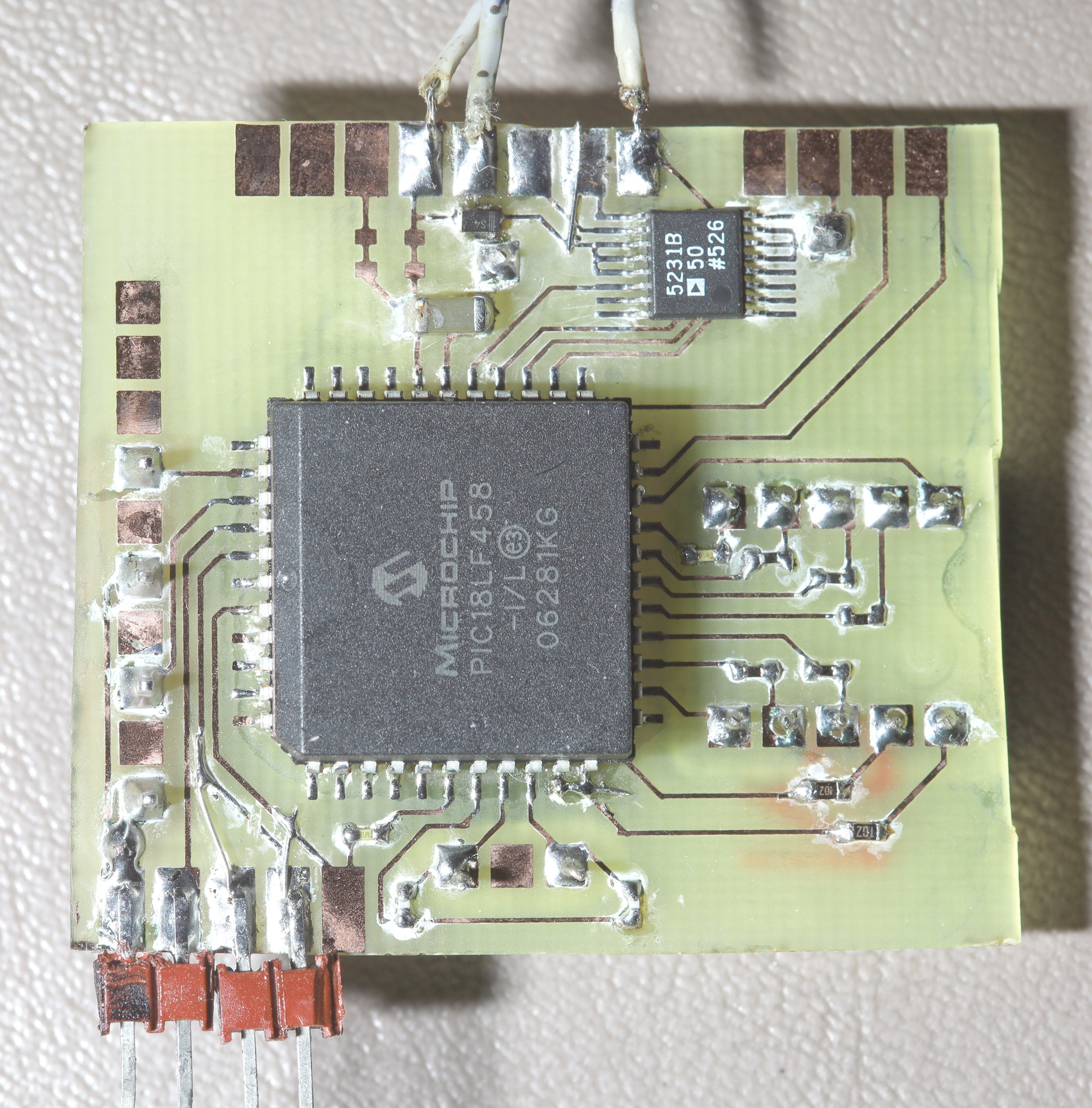
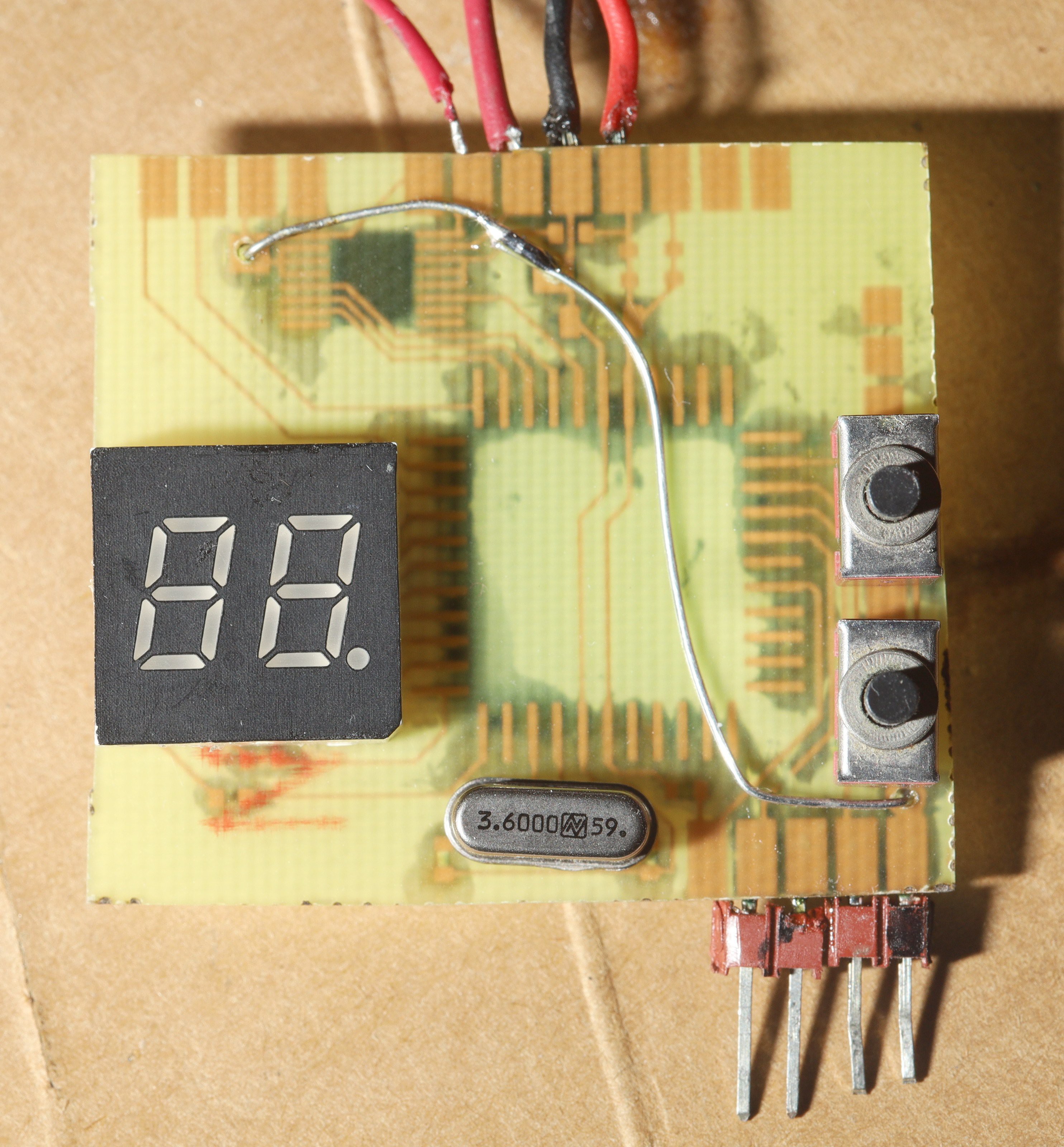
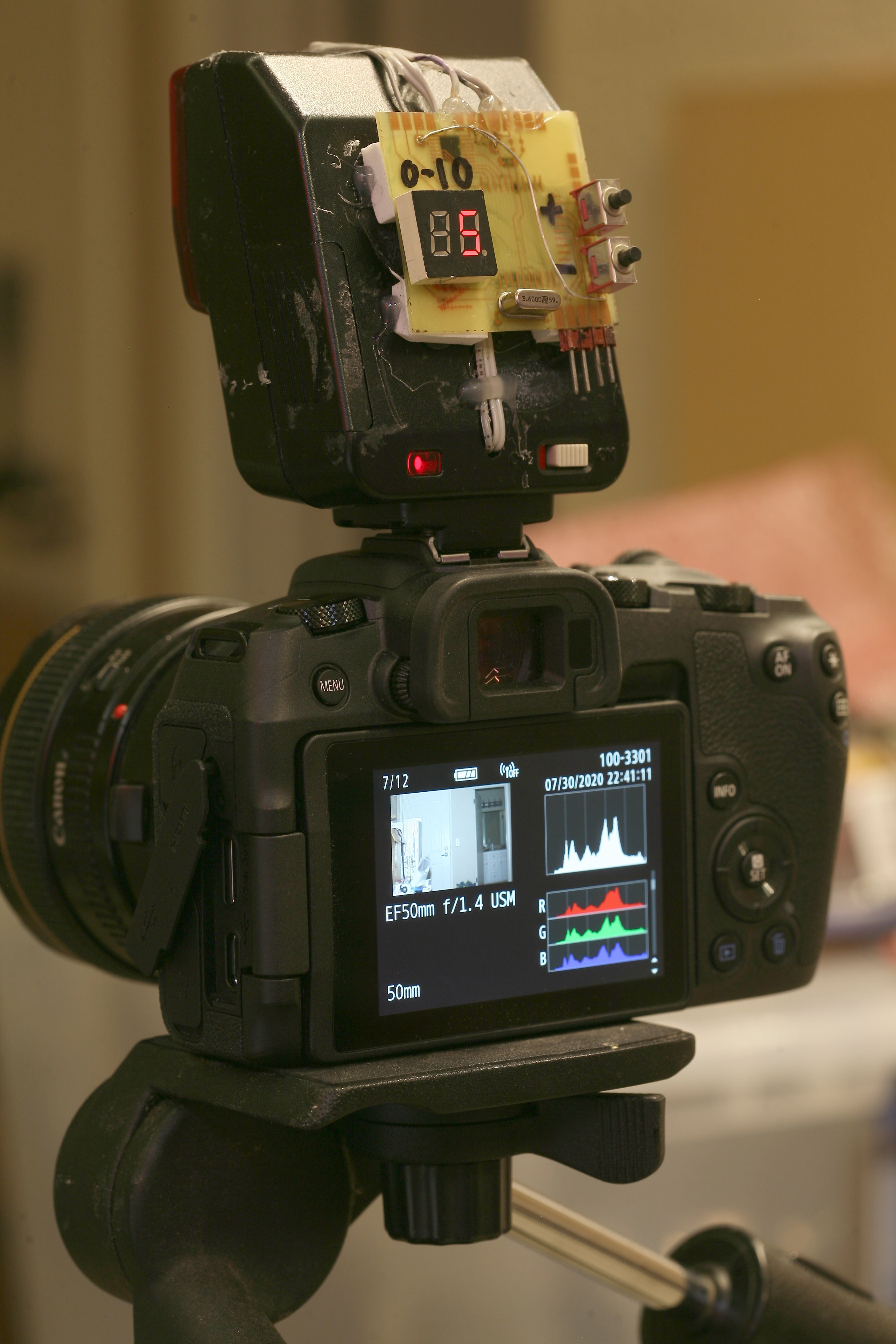
Finally decided there was no way any analog solution would be able to generate the logarithmic resistance in the right range, so an AD5231 + 18LF458 + 25 year old LED panel from a 10 year old preamp circuit reappeared.
Surprised this actually worked. The digital interface runs on the 6V from the boost converter in the flash. It actually generates enough current to power it. The digital pot only works between the voltage rails & within very tight current limits. The boost converter drops to 0 after every flash, resetting the circuit, but the digital pot somehow manages to retain its resistance long enough after the power is lost.
It could have been a lot more compact, but the point was to make it look vintage like everything else. PLCC's still have a coolness factor.
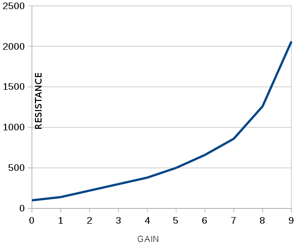
Spent a few hours calibrating all the digital resistances to get the flash as evenly spaced as possible between its lowest & highest setting. This entailed making a logarithmic resistance table. The mane limitation was the smallest resistor step in the low range being 60 ohms. There was no way the high range could have steps as big as the low range.

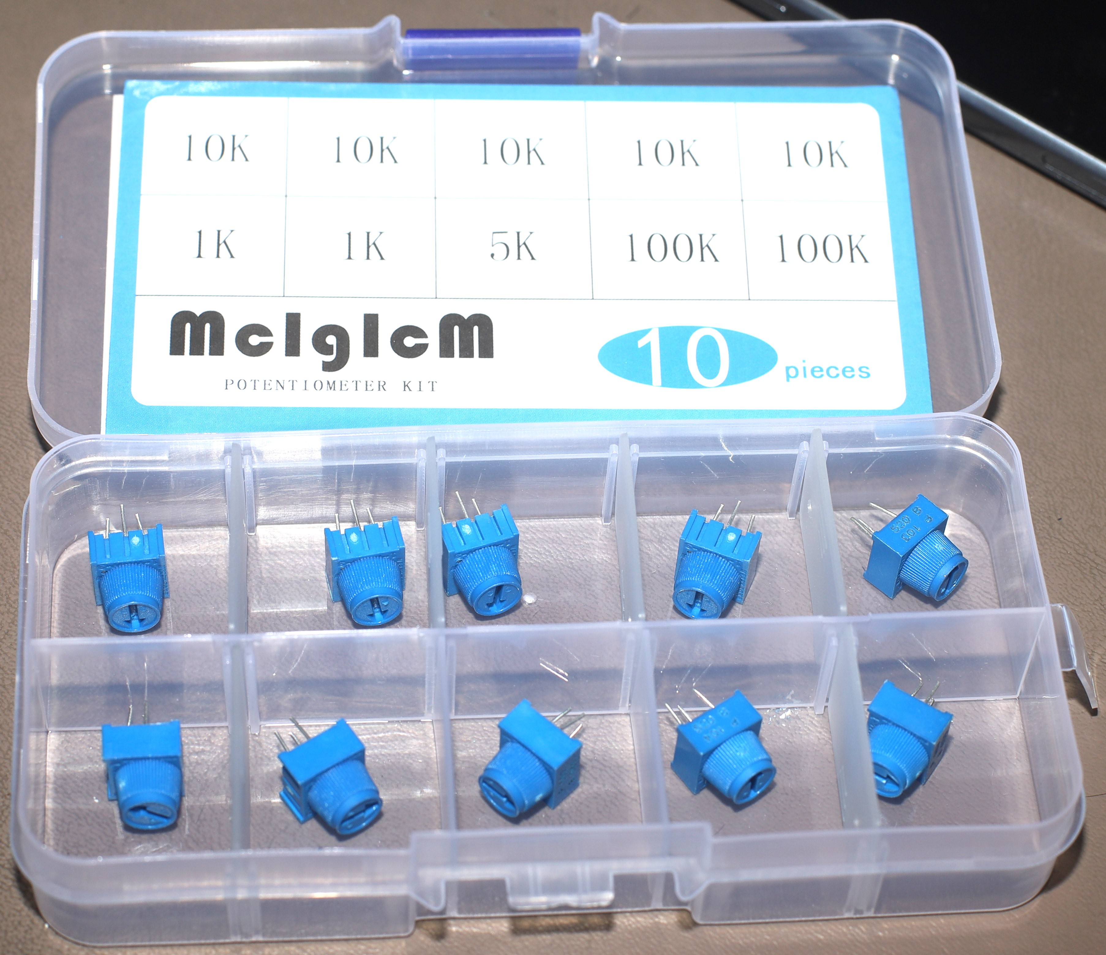
1 casualty of the flash adventure was this set of miniature pots with tactile knobs. In the end, they couldn't have provided the logarithmic range required. They might have been useful in the final product as a replacement for the up/down buttons. They have a lot more weather sealing than the usual pots.
Lions long dreamed of having miniature pots for all their portable gadgets, but they all tend to have screwdriver knobs & the wait required to order them was always too long. Good things come to those who wait, in the mail order world.
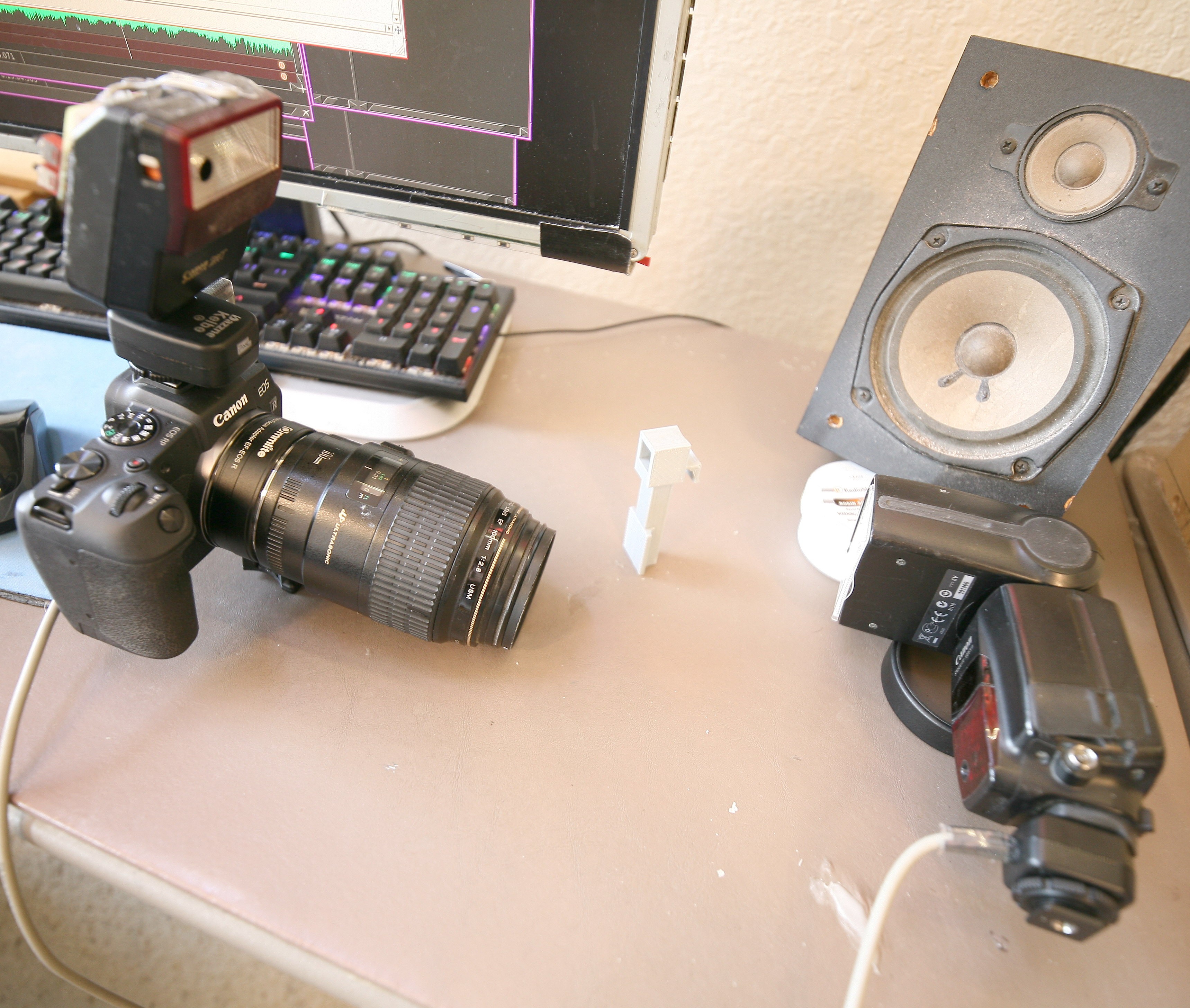
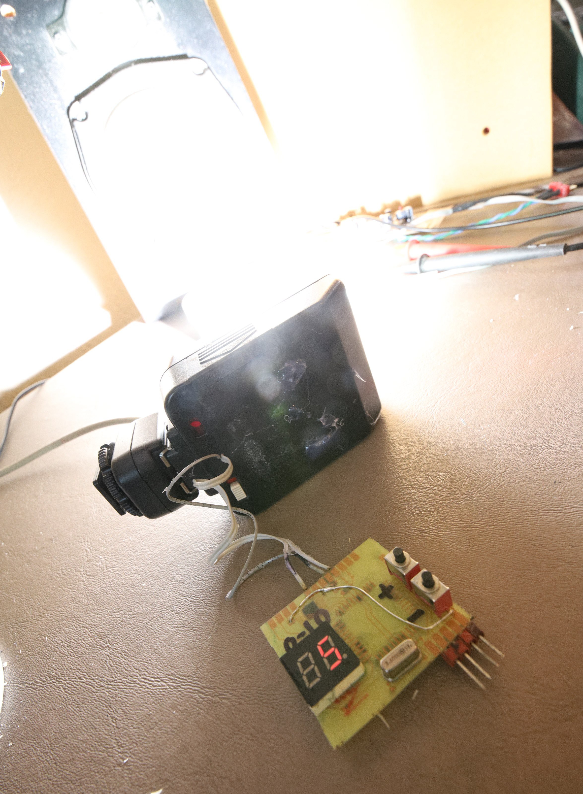
Combine a vintage flash with a less vintage flash to light both sides.
Got an antique flash & know how to discharge the 300V caps without killing yourself? Download the source code.