 Pato Montalvo
The most fundamental component in our device is the air pressure sensors. All of the functionalities and actions revolve around the effective use of this technology, meaning that we need to choose a suitable sensor to have a good overall performance.
While in team discussions, we went over what were the most important aspects that these sensors should have. Like all of our other desired parts, they should be accessible and affordable.
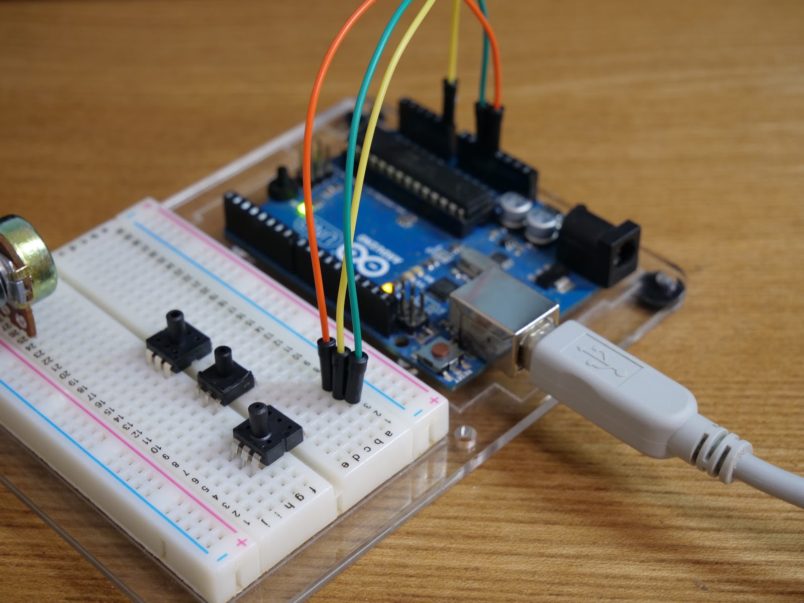
Regarding the technical specs, we started by brainstorming the general design, like Shu described in the previous post. We knew that each one of the harmonica’s air holes would have one individual sensor. This meant that the sensors will be exposed to atmospheric pressure constantly, in contrast with manometric sensors. That narrowed our options to using absolute pressure sensors that measure gauge pressure.
As seen on our BOM log post, we considered numerous options. Shu ordered a couple of them each and we designed a test sequence to determine which sensor is the most appropriate.
We considered the following formula for our design:
Where:
Δp = difference in pressure (desired on the inside vs avg atmospheric pressure on the outside)
ρ = Air density
Q = Hydraulic Head
A2= Area of the orifice
A1= Area of the air hole inlet
For these designs, we also researched the common lung capabilities of the average human. We decided to choose values that would be an average of general human capabilities, (eg. 6 m/s blow airspeed[1] / 0.8 psi exhalation pressure). With the blow speed and the cross-sectional area of the airhole, we calculated the head value and proceeded to iterate until we decided to set for a 2mm diameter orifice.
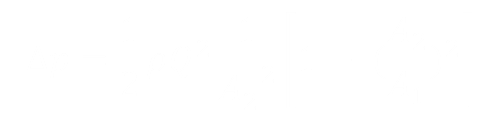
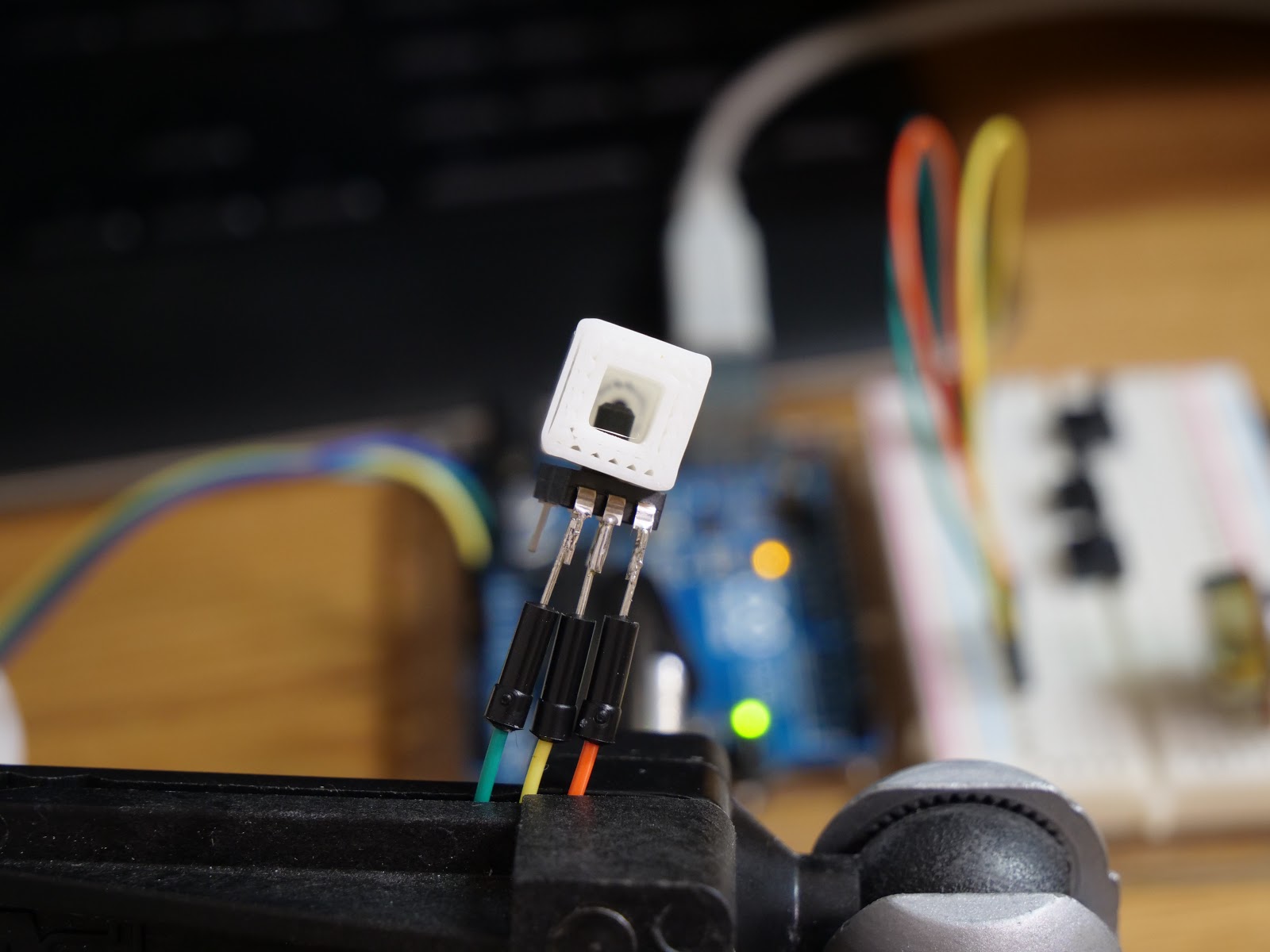
As you can see in the picture below, my partner Shu conducted the tests for each of the sensors and its compatibility with our designs.
An important thing to note is that we are considering a blow and draw functionality in our device, just like in a regular harmonica. That is why we had to make sure that our potential sensor could detect both sip and puff.
After the tests, we concluded that the MPS-2400 series sensors were the most suitable. We are confident we’ve made the right decision choosing this sensor, especially because of the process we used to select it. It will definitely bring the best out of this new adaptive tool.
References:
[1]Flow Through an Orifice
https://mcnallyinstitute.com/13-html/13-12.htm
[2]Human Exhaled Air Energy Harvesting with Specific Reference to PVDF Filmhttps://www.sciencedirect.com/science/article/pii/S2215098616300830
[3]Maximum Static Inspiratory and Expiratory Pressures with Different Lung Volumes
https://www.ncbi.nlm.nih.gov/pmc/articles/PMC1501025/
Discussions
Become a Hackaday.io Member
Create an account to leave a comment. Already have an account? Log In.