 Charlie Smith
With everything simulated we now need to build it. I've decided to use one of the Nordic nRF52 MCUs. There are several which can implement direction finding: nRF52811, nRF52820 and the nRF52833. These all have a 64MHz Arm Cortex M4. However the nRF52833 has an FPU, while the nRF52811 doesn't have hardware USB. There are clearly other differences, such as memory, but these are the main ones. So far we have tested MUSIC on a Teensy 3.6 and 4.1, the 3.6 also has an Arm Cortex M4 with FPU, so the nRF52833 is likely needed, purely for performance reasons. Although we can always collect the data on the nRF and send it to a more powerful MCU such as a Teensy 4.1. I originally designed this for the nRF52820 as I thought it was more available, and is pin compatible with the nRF52833 so I can always upgrade it. However in the end I was unable to get either the nRF52820 or nRF52833 from normal component distributors, but was eventually able to get some nRF52833s directly from Nordic.
So I can use the nRF52833 for the receiver, but as much as I would like to use a pre-made nRF24L01+ for the transmitter, I unfortunately can't as the transmitter needs to be able to enable a continuous tine extension (CTE) at the end of each data packet. However, all this means is that I should design a single transmitter/receiver to be used at each side, and then allow for changing the antenna on the receiver to go to the antenna array. For this array to work, the MCU needs to switch between each antenna, so I also need to break out some GPIO, and while I'm at it I will break out all of it so the board can be used for any future projects:
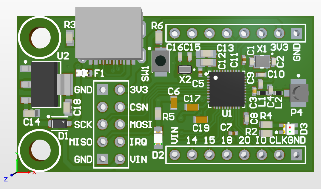
This is a fairly simple design (it looks quite complicated as I labelled everything) but really it just implements a standard design from Nordic, while also having a complete overkill of a LM1117-3V3 regulator as I want it to run at 3.3V to make interfacing with anything else easier. I also added a bi-colour LED, reset switch and USB connector. For the USB, a friend keeps pestering me to use USB-C so I did, although I cheated slightly by using a USB 2.0 only one which has a single row of connectors making routing and soldering it a lot easier (Its a DX07S016JA1R1500 if anyone else wants to use it). I'm also using a U.FL connector for the antenna as they are much cheaper than SMA and you can get very cheap U.FL dipole antennas from eBay.
We also need a second PCB for the antenna array. For now I'm planning on using an 8 antenna circular array. As such I need to be able to switch between each of these antennas. Looking at the datasheet for the nRF52833 we find this: 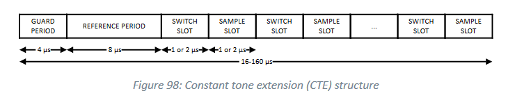 We get a 1μs or 2μs switch slot, so ideally we need to be able to switch faster than this. This isn't a huge requirement, as we can continue switching during one sample slot, but then ignore the sample giving up to 6μs switching time. Of course this does make the entire operation take longer so isn't idea. One option for the RF switch is the HMC253AQS24E. This is SP8T so can switch 8 antennas all in a single chip, and has a switching speed in the tens of nanoseconds. However it is rather expensive and can't be used if we wanted to increase the number of antennas at a later date. An alternative option is a number of SP4T chips such as the PE42442. Of course we need 3 of these to get 8 antennas, but if at a later date I wanted to, I can use 4 of them to get 12 antennas, or 5 for 16 antennas. This PCB seems much simple, but is by far the most difficult one I've had to do so far:
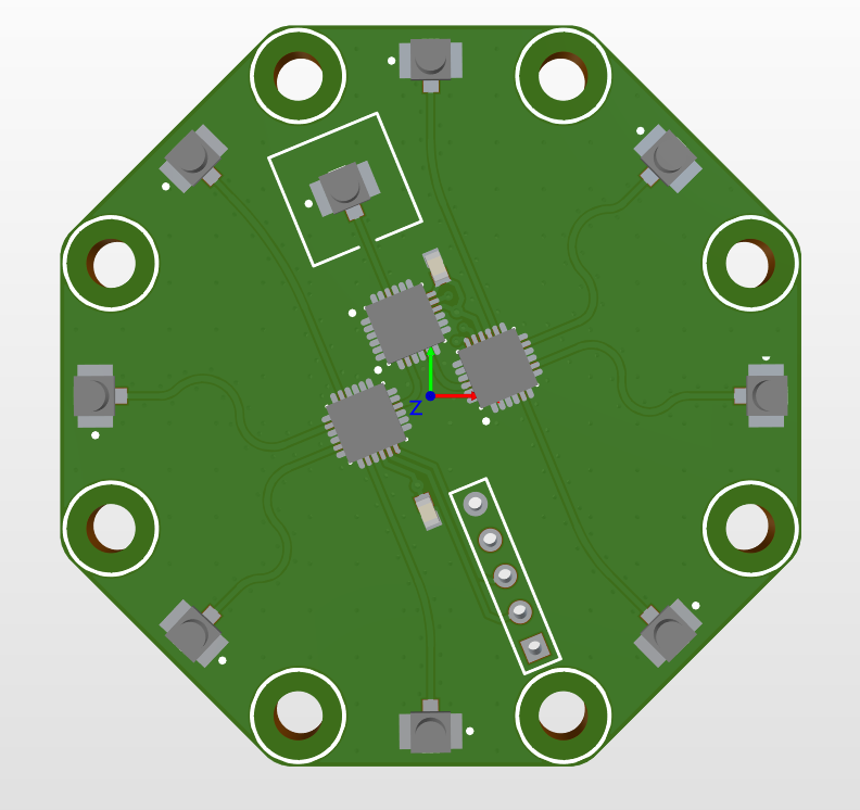 The main problem with this board is that everything needs to be inductance and length matched to allow for ideal operation. I also ended up using a 4 layer PCB so that when the PCBs are made by JLCPCB I can get a controlled impedance PCB (and they put the price down shortly before I ordered these which was nice). This board was also a pain as everything is at an angle, which did result in me finally learning how to use grids in Altium (which is going to be really useful in a bit over a year when I leave uni and wont have a key for Altium any more). I also to add lots of mounting hols on this, as there will need to be some guide to hold the antennas in place above the board.
So that's the boards designed, hopefully they work and the RF performance isn't too dreadful.
Discussions
Become a Hackaday.io Member
Create an account to leave a comment. Already have an account? Log In.